
Practical repairs · Assembly access · P.R.I.N.T. Method™
The holes line up. The replacement looks right. Then you reach for the screwdriver—and discover there is nowhere to put it.
Or the part would fit beautifully inside the housing, if only it could get past the lip at the entrance. These are frustrating repairs because the measurements may be correct. What is missing from the plan is the space needed to get the part into position and work on it.
Before you shave plastic off a fresh print or order a smaller version, separate four questions: Can it enter? Can it seat? Can you fasten it? Can you remove it later?
Quick answer: why does a replacement part fit but refuse to install?
A part can match its final mounting position yet lack a clear insertion path, room for the actual tool, or a workable assembly sequence. Check those first. If it reaches its position but binds at a hole, slot, or bottom edge, investigate the local fit instead.
Do not use the screws to drag an unexplained mismatch into place. Stop, identify the first obstruction, and choose a test that isolates it.
A matching outline does not tell the whole story
Imagine a small organizer bracket that sits under a shelf. On the bench, its screw holes match the original. In the organizer, the shelf blocks a straight screwdriver. Making the holes larger would change the fit without creating the missing tool space.
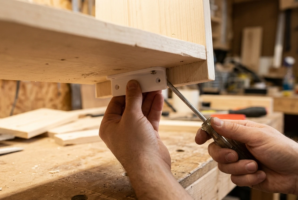
The examples and images illustrate the checks; they are not documentation of a customer repair. Examine the complete assembly rather than the loose part alone.
Check the opening, approach angle, and space to rotate.
Check locating faces, recesses, and nearby surfaces.
Allow for the screw, tool, fingers, and turning motion.
Check release access and the reverse sequence.
1. Follow the insertion path
Start outside the assembly and trace the intended motion. Does the part slide straight in, hook under an edge, or rotate after entering? Note the first point where it stops. A wide flange may fit inside a cavity but never pass through its narrower opening.
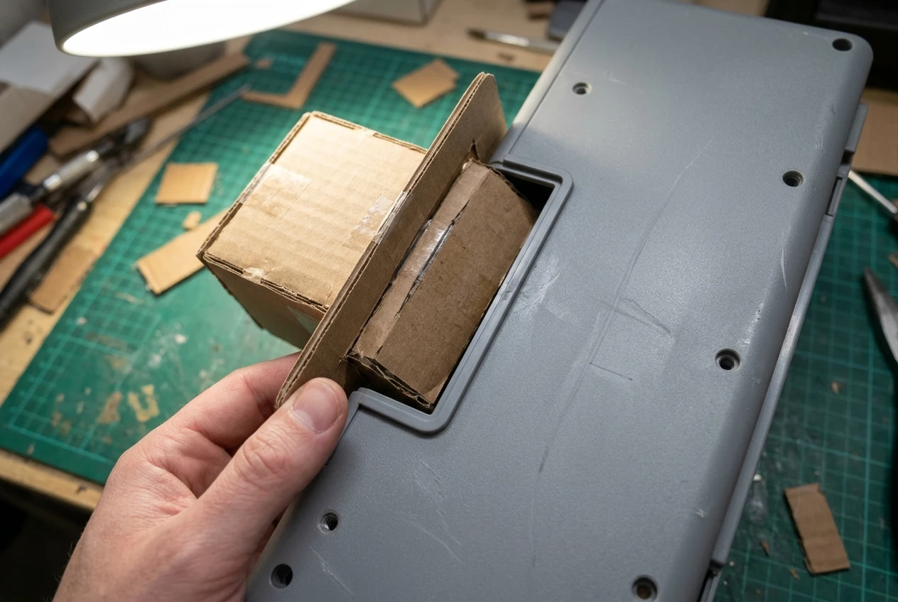
A paper outline or cardboard mockup can help screen an approach. It cannot reproduce a three-dimensional interference or prove how a printed clip will flex. Use it to discover questions, then check the relevant geometry.
2. Check seating before tightening
With the assembly safely accessible, check whether the replacement rests against its intended locating surfaces before fastening. Look for debris, a raised edge, an unexpected rib, or a warped mating surface. Do not sand away a locating feature simply because it touches something.
If the problem is a tight interface, use the clearance and fit guide. Prusa’s design guidance explains why fit allowances depend on geometry, orientation, settings, and material; there is no universal clearance that solves every assembly.
3. Bring the actual tool into the check
A visible screw head is not necessarily an accessible screw head. The driver must approach at the required angle, engage properly, and have room to turn. A nut may also need a wrench or a way to hold it while tightening.
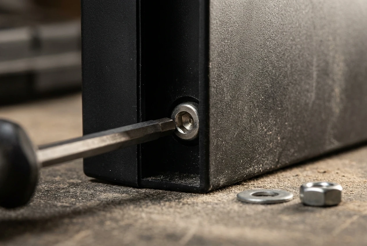
Use the intended screw, washer, nut, and tool during the mockup. A shorter driver may help in some assemblies, but a different fastener or access opening changes the design requirements. Review the connection before making that change.
4. Work backward before calling it finished
Can you release the clip after the cover closes? Can you withdraw the screw without removing an unrelated panel? Can the part leave along the same path it entered?
Write the assembly order in plain language: “Place the bracket, start the fastener, then fit the cover.” If the sequence requires bending something that was not designed to bend, pause. The original may have been installed before another component at the factory.
Use this workflow for accessible, low-consequence parts. Follow the product’s service instructions. Do not remove guards, disturb stored-energy mechanisms, or dismantle electrical equipment just to complete a fit check.
Compare the symptom before changing the model
| What you notice | First useful check | Avoid as the first fix |
|---|---|---|
| Part cannot pass the opening | Entry envelope and rotation space | Scaling every dimension down |
| Part enters but will not sit flat | First contact point and locating surfaces | Pulling it flat with screws |
| Holes align; driver will not reach | Tool approach and assembly order | Enlarging the holes |
| Cover closes; release is hidden | Release access in the closed assembly | Making the latch harder to flex |
| One slot grips; everything else clears | Local clearance, print edge, and mating dimensions | Changing the whole model’s scale |
If the same feature keeps breaking during installation, also read why a plastic part keeps breaking in the same spot. Record the motion that precedes the break before deciding the next version simply needs more material.
Before another full print, test the first obstruction
“Print it again” is a production instruction. “Check whether the flange clears the opening” is a useful test goal.
For an entry problem, a simplified prototype can preserve the outside envelope while omitting decorative detail. For tool access, retain the fastener position and nearby walls. For a flexible latch, preserve the working feature and its support; a thin outline is not representative.
Label the revision and record what you changed. Keep the intended material, orientation, and relevant print settings when they affect the test. Once a promising change works, confirm it in the complete assembly. A partial prototype can miss a collision elsewhere.
CAD can help when the surrounding geometry is available. Autodesk documents an interference tool for selected bodies and components. A clean check in the final position does not, by itself, establish an unobstructed installation route. Examine intermediate positions and tool space as separate questions.
Send the space around the part—not just the part
A close-up of the replacement is useful. A view showing the opening and neighboring components often explains why it cannot be installed.
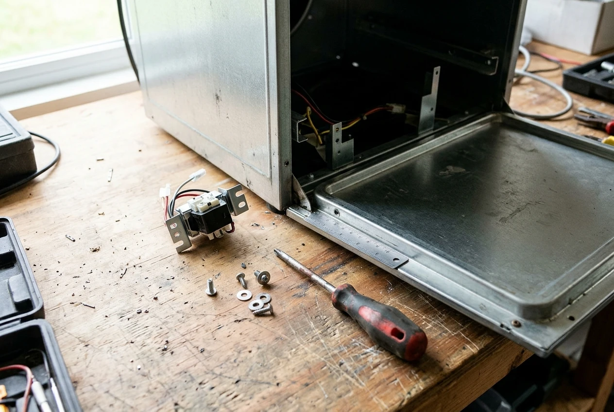
Show the opening, nearby walls, and where the part belongs.
Show where movement stops, without forcing the part.
Include the tool and hardware beside the access point.
Show holes, lips, slots, and a clearly identified reference measurement.
Use the part-measurement guide to separate measurements from estimates. If part of the original is missing, the missing-piece guide explains which surviving references may help.
Your P.R.I.N.T. installation planner
Fill this in before another revision. Entries stay in the page only; they are not saved or sent. Copy your notes into your own document or the project form before leaving.
Take your notes to Kevin’s project form
The link opens the intake page; it does not transfer these entries automatically.
Want a reusable planning reference beside your printer? Print It Practical: 3D Printing for Beginners includes project planners and a fillable worksheet. Use this installation check alongside those project notes.
Should you buy anything to solve this?
Start with the part, its surroundings, your measuring tools, and the intended hardware. A faster printer will reproduce the same blocked access if the design stays unchanged. Consider equipment only after you know which capability your project actually lacks.
Optional equipment resources for makers
Affiliate disclosure: I may earn a commission if you buy through these links, at no additional cost to you.
If you already plan to print your own prototypes, compare Creality printers against your part size and material requirements. For irregular existing surfaces, explore 3DMakerpro scanners as a possible capture tool; still verify critical dimensions and assembly access.
Before an already-planned purchase, review current Creality offers, student eligibility terms, or material offers. Confirm eligibility, region, exclusions, and final checkout terms. Buy the material your project needs, not extra rolls solely to reach a discount.
Four-question knowledge check
Select one answer per question to reveal feedback. You can change answers or reset the check. Nothing is submitted.
Frequently asked questions
Should I scale the replacement down until it goes in?
First identify what stops it. Global scaling changes hole spacing, wall thickness, and other dimensions that may already be correct. A local revision or different assembly sequence may be more appropriate.
Can a two-piece design solve an installation problem?
Sometimes. Separate pieces may enter through a restricted opening and join afterward. The joint adds requirements for alignment, fastening, strength, and access, so it needs its own review and testing.
Does a 3D scan prove that the replacement will install?
No. Capturing a surface is different from checking an assembly sequence. Critical interfaces, hidden geometry, the insertion route, and tool access still need evaluation.
What if I cannot send the complete assembly?
Start with clear photos, measurements, the original part if available, and a description of the obstruction. Some projects need an additional fit check or access to the assembly before the design can be confirmed.
Show me where it stops
I review custom and replacement-part projects from Independence, Kentucky. Include a view of the surrounding assembly and explain what happens during installation. You do not need to choose a filament before asking.
Request a replacement-part review
Feasibility, design requirements, budget, and scheduling are reviewed before acceptance.
Which step caught you out?
Tell me in the comments: Did your part get stuck entering, seating, fastening, or coming back out? Describe the part and the first obstruction you noticed. Your example may help another reader recognize the same problem. Use the project form for private drawings, files, or quote requests.
Technical sources: Prusa: Modeling with 3D printing in mind; Autodesk: Detect interferences and coincident faces. These support the fit and CAD principles discussed here. The installation checklist is a practical synthesis, not a manufacturer service procedure or certification test.
