
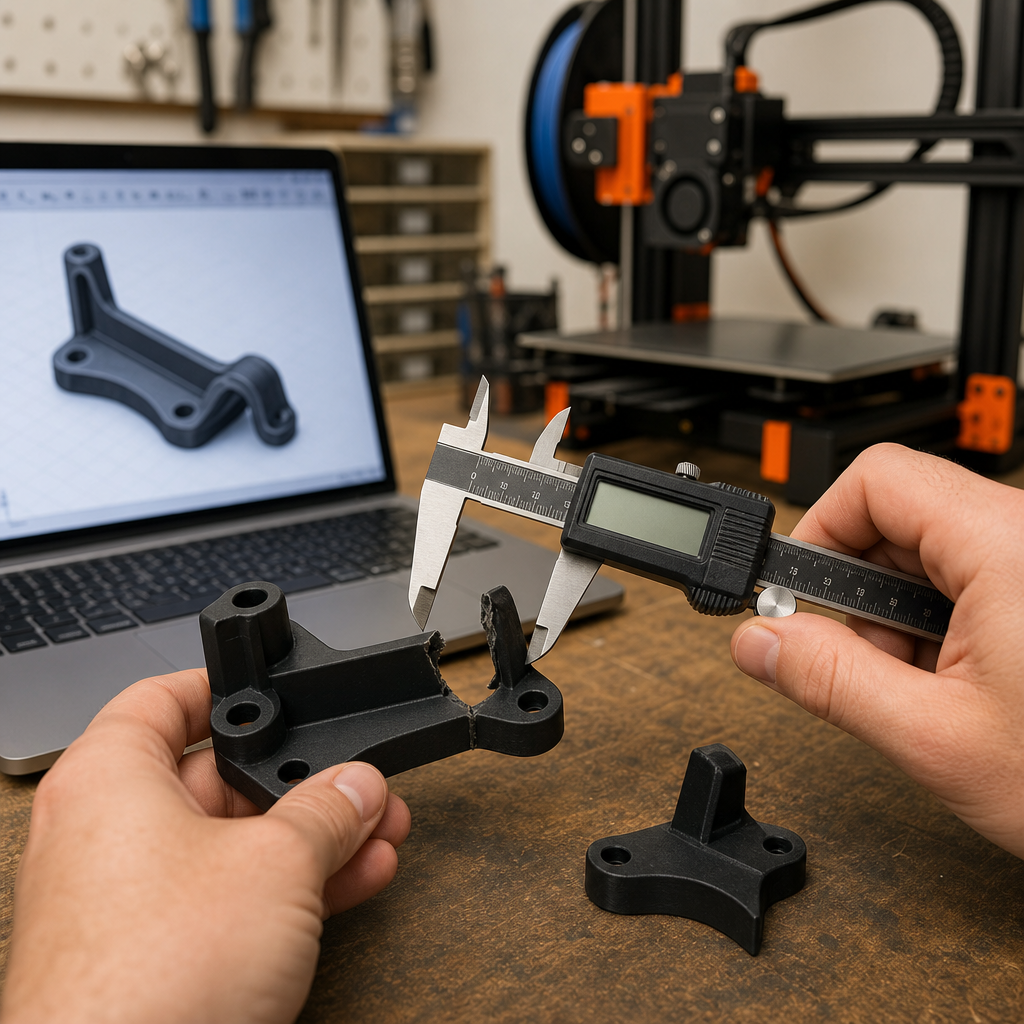
A replacement part can look almost identical to the original and still miss a screw hole, bind in a slot, fail to snap into place, or collide with the surrounding assembly. Good reverse engineering starts by identifying the dimensions that control fit, movement, attachment, and function.
How do you measure a part for 3D printing?
Measure the part’s overall length, width, height, and important wall thicknesses first. Then prioritize every interface: screw holes, slots, clips, tabs, shafts, mounting faces, stops, clearances, and the spacing between them. Use stable reference points, photograph the part from multiple angles, keep every broken fragment, and record what the part must actually do. The measurements that control fit and function matter more than decorative detail.
Start by asking what the part actually does
Before reaching for the calipers, describe the part in one sentence. Does it hold a cover? Position a shaft? Snap over a lip? Space two components apart? Guide a cable?
That answer tells you which dimensions deserve the most attention.
Fit
Which surfaces, holes, slots, tabs, or shoulders determine whether the part can be installed?
Function
What must move, flex, rotate, support, locate, clamp, cover, or remain clear?
Environment
Will the part see heat, sunlight, moisture, vibration, chemicals, repeated use, or sustained load?
Workshop rule: A printer can reproduce the wrong dimensions beautifully. Measuring the job correctly comes before choosing print settings.
Use the P.R.I.N.T. Method™ before modeling
“`Measuring is part of solving the problem—not a separate chore before the “real” design work begins.
“`Problem
Define what failed, disappeared, or needs improvement.
Requirements
Record load, heat, weather, flex, appearance, life, quantity, and safety.
Interfaces
Measure every point where the part fits, clips, slides, screws, touches, or locates.
Next-Best
Choose measurement, scanning, CAD, material, orientation, and manufacturing method.
Test & Tune
Verify the risky interface with a controlled prototype before final production.
What should you measure first?
| Feature | Record | Why it matters |
|---|---|---|
| Overall envelope | Length, width, height, maximum thickness | Confirms the replacement can occupy the available space. |
| Mounting holes | Diameter, depth, spacing, edge distance, countersink or counterbore | A small location error can prevent installation. |
| Clips and tabs | Length, width, thickness, hook depth, angle, flex direction | These features must engage while surviving assembly. |
| Slots and channels | Width, depth, taper, radius, distance from reference surfaces | Too tight can bind; too loose may fail to guide or retain. |
| Shafts and posts | Diameter, flats, insertion depth, shoulder location | These often control alignment, rotation, or torque transfer. |
| Mating faces | Contact area, angle, curvature, stops, neighboring gaps | The visible outline can look correct while the contact geometry is wrong. |
| Reference spacing | Center-to-center and face-to-feature distances | Relative position is often more important than one isolated dimension. |
Use one reference point whenever possible
Measurements become unreliable when each one begins from a different uncertain location. Choose a flat mounting face, centerline, shoulder, or undamaged edge and relate important features back to it.
Better: common reference
Measure the first hole from the mounting edge, then the second hole from that same edge or from the first hole’s centerline.
Riskier: chained measurements
Measuring one uncertain feature from another can allow several small errors to accumulate across the model.
A practical seven-step measurement process
Write one sentence explaining what the part holds, locates, guides, covers, spaces, or connects.
Note cracks, wear, stripped holes, heat damage, broken clips, missing pieces, or deformation.
Take a wide view before the close-ups so the part’s orientation and surroundings remain clear.
Record length, width, height, thickness, and the space available around the part.
Prioritize holes, tabs, slots, clips, mating faces, pivots, shoulders, and clearances.
Include load, heat, sunlight, water, chemicals, vibration, motion, and expected service life.
Identify the riskiest interface and prove it before spending hours on the final print.
How to get more useful measurements from digital calipers
Zero before measuring
Close the jaws gently, confirm zero, and recheck it if the readings begin looking inconsistent.
Measure more than once
Repeat critical dimensions from the same reference and compare the readings before committing them to CAD.
Use the correct measuring surface
Outside jaws, inside jaws, depth rod, and step surfaces solve different measurement problems.
Do not squeeze flexible plastic
Thin molded walls and clips can deflect under the jaws and make a dimension look smaller than it really is.
Do not claim more precision than you measured. A ruler, photograph, inexpensive caliper, and precision measuring system do not provide the same confidence. Honest uncertainty is useful design information.
Photographs are part of the measurement package
Dimensions provide numbers. Photographs explain what those numbers belong to.
- Photograph front, back, top, bottom, and both sides.
- Add angled views that reveal depth and hidden transitions.
- Include a wide shot showing where the part installs.
- Photograph the mating component separately.
- Place a ruler in the same plane as the feature when useful.
- Use even lighting that keeps edges visible.
- Show every surviving fragment.
- Mark the broken, worn, or missing area.
One close-up rarely tells the whole story. A wider photograph can reveal orientation, neighboring obstructions, screw access, and available clearance that are invisible in an isolated part photo.
Keep the broken pieces—even the ugly ones
A cracked tab or chipped corner may preserve wall thickness, internal ribs, an original radius, clip geometry, or evidence of the direction in which the part failed.
That failure evidence matters because an exact copy is not always the best replacement. A weak sharp corner might benefit from a radius. A stripped plastic hole may need a different fastener strategy. A heat-damaged PLA component may point toward a different material.
The goal is not necessarily to duplicate the old plastic. It is to create the next practical part that fits the assembly and performs the required job.
Measure, scan, or rebuild in CAD?
| Method | Best for | What it may miss |
|---|---|---|
| Manual measurement | Holes, wall thickness, shafts, spacing, mounting geometry, straight features | Complex freeform surfaces |
| 3D scanning | Curves, contours, organic surfaces, surrounding reference geometry | Hidden features, intended dimensions, missing broken geometry, required clearance |
| CAD reconstruction | Editable geometry, symmetry, controlled features, missing sections, redesign | It is only as reliable as the measurements and reference information supplied |
| Combined workflow | Complex replacement parts with both sculpted and precision features | Still requires testing and engineering judgment |
For a deeper look at that decision, read Can a 3D Scanner Replace CAD? .
Measurement is not the same as clearance
Measuring a 10 mm shaft does not automatically mean the mating printed hole should also be modeled at exactly 10 mm. The amount of space needed between mating features depends on the desired fit, printer, material, orientation, first layer, geometry, and process behavior.
Rather than turning this measuring guide into another tolerance guide, continue with 3D Printing Tolerances Explained: Why Parts That Look Perfect Still Don’t Fit .
Formlabs also provides a useful outside reference explaining clearance, transition, interference, and other engineering-fit concepts .
Prove the riskiest feature before printing the whole part
If one clip, shaft, hole pattern, or sliding feature determines whether the replacement succeeds, isolate that geometry and test it first.
A short fit-check print can reveal more useful information than a several-hour full prototype that repeats the same untested interface.
Use Why 3D-Printed Replacement Parts Need a Test Fit for the next stage of the workflow.
The 30-second measurement check
Before modeling the replacement, can you answer these three questions?
Where does it locate?
Which surface, edge, shoulder, hole, or centerline establishes the part’s position?
Where does it connect?
Which screw, tab, clip, shaft, groove, or mating face holds it in place?
What happens if it is wrong?
Will it simply look uneven—or could it bind, crack, loosen, collide, or fail?
If one answer is unclear, that is probably where the next photograph or measurement should go.
What should you send with a custom-part request?
You do not need a finished STL or engineering drawing to begin. A useful project packet can start with the original part, photographs, measurements, and a plain-language explanation.
- What the part must accomplish
- Photos from several directions
- A photo showing where the part installs
- Overall length, width, height, and thickness
- Critical hole, slot, tab, shaft, and spacing dimensions
- Load, heat, weather, movement, and exposure information
- Expected quantity
- Any STL, STEP, OBJ, sketch, drawing, or PDF available
A complete packet does not guarantee that a part should be 3D printed. It provides enough information for a more useful first review.
Continue the replacement-part workflow
Part no longer available?
Need closer dimensional control?
Explore Precision 3D Printed Parts .
Want the complete planning system?
Continue with P.R.I.N.T. It: Practical 3D Printing for Beginners .
New printer owners can also start with 3D Printing for Absolute Beginners , while broken clips and brackets have their own service guide at Broken Brackets and Clips Replaced with 3D Printing .
Four-question knowledge check
Open each question after choosing your answer.
1. Which dimensions should receive the highest priority?
Prioritize the interfaces—the surfaces and features where the part mounts, clips, slides, screws, locates, supports, or contacts another component.
2. Why should related measurements use a common reference?
A common mounting face, centerline, shoulder, or stable edge reduces accumulated error and makes the measurements easier to reproduce correctly in CAD.
3. Can a 3D scanner replace all manual measurements?
No. A scanner can capture visible surface geometry, but critical holes, hidden features, damaged geometry, wall thicknesses, and required clearances often still need direct measurement or CAD reconstruction.
4. Is an identical copy always the best replacement?
No. If the original failed because of a weak transition, unsuitable material, poor fastener design, or harsh operating conditions, the replacement may benefit from a practical redesign.
Frequently asked questions
Can a broken part still be measured for 3D printing?
Often, yes. Broken fragments, matching components, symmetry, mounting locations, photographs, and known reference dimensions may provide enough information to reconstruct the important geometry.
Do I need digital calipers to request a quote?
No. Clear photographs, a ruler or tape measure, and a useful description can be enough for an initial review. Calipers become more useful when small holes, walls, depths, shafts, and close-fitting features matter.
Can you measure a part accurately from a photograph?
Photographs can provide approximate scale when a reliable reference is visible in the same plane, but camera angle and perspective can distort dimensions. Direct measurement is preferable for critical interfaces.
What if the original part is completely missing?
The surrounding assembly may still provide useful design information. Mounting holes, available space, matching left- or right-hand parts, manuals, photographs, and mating components can help reconstruct what is needed.
Why shouldn’t I model mating parts at exactly the same size?
Real printed surfaces require intentional fit planning. Printer behavior, extrusion, material, orientation, surface texture, and the type of joint all affect the clearance required.
Should I measure the broken shape exactly?
Record the surviving geometry, but also identify deformation, wear, cracks, melted areas, and missing sections. A damaged dimension may describe the failure rather than the original design.
Have a discontinued, damaged, or hard-to-find plastic part?
Send photographs, measurements, broken fragments, available files, and a description of what the part must do. The first review can focus on fit, function, material requirements, printability, and the most practical next step.
Custom-part feasibility depends on the available reference information, required fit, material demands, operating environment, load, quantity, budget, and consequences of failure. Measurements taken with ordinary tools may include uncertainty, and not every damaged or discontinued component is an appropriate candidate for FDM 3D printing.
