
Functional 3D Printing Guide • Updated September 2026
The CAD model says the part should fit. The print looks clean. Then the pin stops halfway into the hole. That is the moment when “accuracy,” “tolerance,” and “clearance” stop being technical vocabulary and start costing you filament.
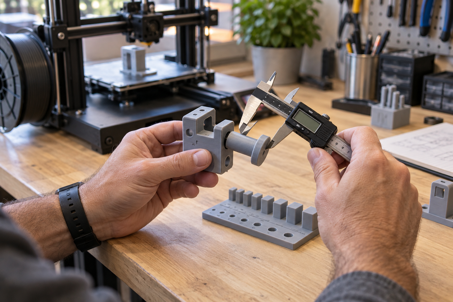
I see this constantly with functional parts. A bracket can look almost perfect and still miss the job by a fraction of a millimeter. A lid can be the right size and still bind. A snap can engage once and then crack. A hole can be centered correctly but print too tight for the screw or shaft it was designed around.
The fastest fix is usually not “buy a better printer.” It is to figure out where the fit error came from, then change the right variable instead of scaling the entire model and hoping.
Quick answer
How much tolerance should you use for 3D printing?
There is no universal 3D-printing tolerance or clearance that works for every printer, material, orientation, hole, pin, hinge, or snap fit. For functional FDM parts, I start with a small test coupon that reproduces the actual interface, print it with the same material and orientation planned for the final part, let it cool, measure it, and adjust one variable at a time.
As a useful reference point, Prusa notes that mating parts need intentional tolerance and suggests at least 0.3 mm as an initial value for movable parts, while UltiMaker gives 0.6 mm as a general gap for components printed together. Those numbers are starting guidance—not guarantees for your machine or design.
Send the file, broken original, photos, measurements, or a description of what the part must fit. I can review the geometry, interfaces, material demands, and practical next step.
Affiliate disclosure: This guide includes a COEX partner link. If you buy through that link, 3D Printing by Kevin may receive compensation at no extra cost to you. Recommendations stay tied to the job, not the commission.
Tolerance, clearance, and accuracy are not the same thing
This distinction matters because a surprising number of failed fits begin with the wrong word—and therefore the wrong fix.
| Term | What it means | Example | What you change |
|---|---|---|---|
| Dimensional accuracy | How closely the printed dimension matches the intended CAD dimension. | A 25.00 mm feature prints at 24.82 mm. | Calibration, flow, first layer, compensation, material/process control. |
| Tolerance | The acceptable amount a dimension may vary and still perform its job. | A bracket width is acceptable from 49.8 to 50.2 mm. | The design requirement and inspection limit. |
| Clearance | The intentional gap between two mating surfaces. | A sliding tab is designed smaller than the slot around it. | The CAD dimensions of the mating parts. |
| Fit | The real-world result when the printed parts meet. | Press, snap, slide, rotate, locate, or remain loose. | Potentially all of the above. |
If the printer makes a 10 mm pin consistently at 10.15 mm, that is an accuracy problem. If you designed a 10 mm pin for a 10 mm hole, that is a clearance problem. If the assembly can still work from 0.2 to 0.4 mm of gap, that range is part of your functional tolerance.
Do not use one word—“tolerance”—to describe every fit problem. Measure the printed feature, identify the actual interface, and decide whether the problem belongs in the printer, the slicer, the CAD model, or the assembly method.
Infographic: Why a “perfect” CAD fit can fail after printing
The point is not that FDM is inaccurate. The point is that functional fit is the combined result of design, machine behavior, material, orientation, cooling, slicing, and the geometry of the interface itself.
Prusa makes the same basic point in its design guidance: there is no single universal tolerance because model size, orientation, geometry, calibration, settings, and material all matter. That is why a small fit coupon usually tells you more than somebody else’s favorite number.
Read Prusa’s official modeling-and-tolerance guidance.
Practical starting clearances I would test first
I treat the values below as coupon starting points, not promises. They describe the gap between adjacent mating surfaces. A calibrated machine, clean first layer, dry material, and predictable orientation may let you run tighter. A large part, rough surface, flexible material, or print-in-place joint may need more room.
| Fit goal | Starting gap to test | What I want to see | Likely next move |
|---|---|---|---|
| Very snug locator | About 0.10–0.20 mm between mating surfaces | Parts locate firmly without forcing or shaving plastic. | Increase slightly if insertion marks or distortion appear. |
| Removable slip fit | About 0.20–0.30 mm | Assembly by hand with little resistance and no binding. | Tighten only after the real material and orientation are tested. |
| Moving hinge or slider | Start around 0.30 mm or more | Motion begins freely after cleanup and cooling. | Add room if texture, seam position, or layer stepping causes drag. |
| Print-in-place movement | Often 0.30–0.60 mm or more | Adjacent surfaces remain separate throughout the print. | Use the printer/material combination to determine the real minimum. |
| Snap fit | Do not choose by clearance alone | Correct engagement plus enough flex without whitening or cracking. | Adjust hook depth, beam thickness, root radius, orientation, and material—not only the gap. |
A successful fit test does not establish structural capacity, fatigue life, temperature resistance, chemical compatibility, or suitability for a regulated or high-consequence application.
For comparison, Prusa suggests at least 0.3 mm as an initial value for movable parts. UltiMaker’s FFF design guidance recommends a 0.6 mm gap when components are printed together so they can move after printing. Those two reputable references are useful precisely because they show why “the correct tolerance” depends on how the joint is made.
See UltiMaker’s official FFF design guidance.
Why holes are often the first place a functional print exposes the problem
Outside dimensions can look excellent while holes still print tight. That is one reason I do not scale an entire model just to rescue one screw hole. Scaling changes every dimension—including features that may already be correct.
Instead, I check the cooled part with calipers, confirm the first layer is not flaring into the hole, inspect the slicer path, and compare the result with the design size. If the error is repeatable, a hole-specific or XY contour compensation may be more appropriate than resizing the whole object.
For the measurement side of the workflow, use my guide to better measurements for 3D-printed parts. If the machine itself needs attention, work through the 3D-printer calibration guide before editing every model you own.
The first layer can ruin an otherwise correct fit
Elephant foot is one of the sneakiest causes of “almost fits.” The first layer spreads slightly beyond the intended edge, so a tab that should slide into a channel catches at the bottom. The rest of the part may measure correctly.
That is why I measure above the first-layer flare before deciding the entire print is oversized. Slicer elephant-foot compensation, a small bottom chamfer, and correct first-layer setup can fix a bottom-only interference without changing the complete model.
If you are chasing several symptoms at once, use the 3D-printing troubleshooting guide and change one variable at a time.
Material changes the way clearance feels
Two parts can share the same nominal clearance and behave very differently in PLA, PETG, ABS, or a flexible material. Stiffness changes how easily a snap bends. Surface texture changes sliding friction. Cooling behavior can alter final dimensions. Moisture can affect extrusion consistency and surface quality.
This is why I test the final joint in the actual material whenever fit matters. A PLA coupon is useful for proving geometry, but it does not automatically prove that a PETG clip or ABS housing will behave the same way.
I use COEX filament in my own workflow because predictable material helps remove one source of variation. If you want to compare current COEX materials, use my partner page and confirm the final discount and product details at checkout.
Comparison: Should you fix the CAD, printer, slicer, or finished part?
| What you observe | Best place to investigate first | Why |
|---|---|---|
| Every outside dimension is consistently off | Printer/profile calibration | The error may be systematic rather than specific to one joint. |
| Only one hole or slot is too tight | CAD or feature-specific compensation | Do not disturb dimensions that are already correct. |
| Only the bottom edge interferes | First layer / elephant-foot correction | A bottom-only flare is different from full-part scaling error. |
| The same file changes fit with a new material | Material profile and test coupon | Thermal and extrusion behavior changed. |
| The joint fits after light drilling or reaming | Decide whether post-processing is acceptable | For one-offs, controlled finishing may be simpler than redesigning; for batches, redesign may save labor. |
| Two print-in-place pieces fuse together | Designed gap, flow, first layer, orientation | Adjacent toolpaths never achieved the separation the mechanism needed. |
Infographic: My three-print fit test
Cut the design down to the hole, pin, slot, snap, hinge, or locating feature that actually controls the fit.
Record the designed size, measured size, material, orientation, layer height, and the way the parts actually assemble.
Adjust the clearance, compensation, first-layer behavior, or geometry. Do not change five slicer settings and destroy the evidence.
A tiny coupon that prints in 12 minutes can be more valuable than a beautiful six-hour prototype that repeats the same untested interface twenty times.
Use the P.R.I.N.T. Method™ to solve fit problems without guessing
The complete P.R.I.N.T. Method™, printable planners, troubleshooting reference, and functional-print workflow are built into my P.R.I.N.T. It Practical — 3D Printing for Beginners ebook.
Fit & Clearance Planner
Use this before committing to the final print. You can fill it in on-screen while planning, then copy the answers into your project notes.
Four-question knowledge check
Choose your answer before opening each explanation.
1. A 10 mm pin and a 10 mm hole are modeled at exactly the same size. Is that automatically a good sliding fit?
2. One screw hole prints too small, but the rest of the part measures correctly. Should you scale the entire model?
3. Why should a tolerance coupon use the final material and orientation?
4. A print-in-place hinge is fused. What is the most useful next test?
Frequently asked questions about 3D printing tolerances
What is a good tolerance for FDM 3D printing?
There is no single value that applies to every FDM printer and part. The acceptable dimensional tolerance depends on the machine, geometry, size, material, orientation, settings, and what the part must do. Define the functional limit first, then test the real interface.
How much clearance should I leave between two 3D-printed parts?
For separately printed parts, a small interface coupon around 0.10–0.30 mm between adjacent surfaces can be a useful place to begin testing, depending on whether you want a snug or freer fit. Moving and print-in-place parts often need more. Treat every number as a starting point for your printer—not a universal rule.
Why do 3D-printed holes come out smaller?
Holes can be affected by extrusion width, path geometry, cooling, first-layer compression, orientation, and material behavior. Measure the cooled feature and determine whether the error is local to the hole or part of a larger dimensional problem.
Can I fix fit problems with XY compensation?
Sometimes. If the dimensional error is predictable and the slicer offers an appropriate feature or contour compensation, it can be useful. But compensation should not replace a correctly designed clearance or hide a poorly calibrated process.
Should I drill printed holes to final size?
For some one-off functional parts, drilling or reaming is a practical way to obtain a clean final hole. If you are producing a batch, however, repeated manual finishing may cost more time than correcting the design or process.
Does a 3D scanner solve tolerance problems?
No. A scanner can help capture complex shape, but critical holes, mating surfaces, snap features, and clearances still need dimensional verification and often clean CAD reconstruction. The scan records geometry; it does not decide the fit you need.
The best tolerance is the one you proved on your part
I would rather spend fifteen minutes on a small coupon than six hours discovering that a finished housing needs to be reprinted because one slot is 0.2 mm too tight.
That is the practical shift: stop asking for one magic tolerance number and start testing the actual interface. Define what the joint must do. Measure the surfaces that matter. Use the real material. Keep the orientation. Let the part cool. Change one variable. Save the successful result.
That is how a part goes from “close enough on screen” to useful in the real world.
Send the file, photos, measurements, quantity, and intended use. I’ll review the interfaces, printing route, material demands, and whether a controlled fit test should happen before final production.
What has been your most stubborn fit problem?
Was it a hole that always printed small, a lid that bound after cooling, a snap that cracked, or a print-in-place joint that fused together? Leave a comment with the printer, material, and interface. Your example may help another maker diagnose the same problem.
Fact-check sources: Official Prusa Knowledge Base guidance on modeling, tolerances, and printer precision; official UltiMaker FFF design guidance on moving-part gaps, holes, nozzle size, and elephant-foot effects. Internal links and project-intake/ebook pages were checked against 3DPrintingbyKevin.com during the September 10, 2026 site review.
