
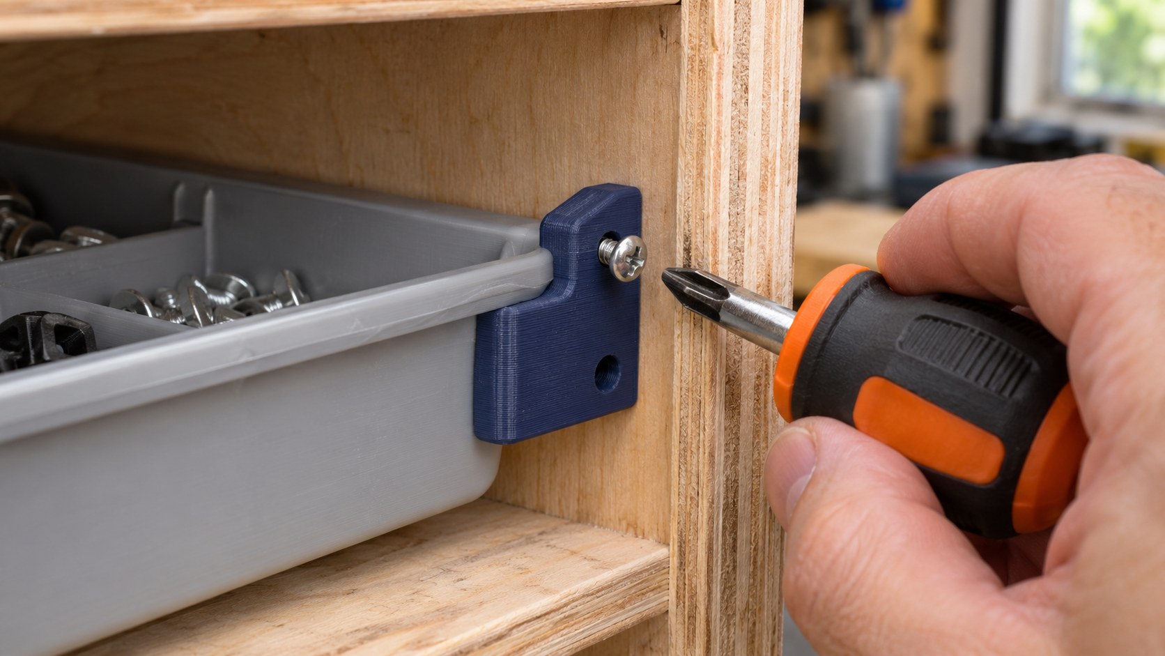
The bracket sits flat. Both holes line up. Then the screwdriver handle hits the side of the cubby, and the bit slips out of the screw head.
Before you open the slicer again, try the part where it belongs with the actual hardware and tools. Find the first thing that gets in the way. A different tool or assembly order could save you a reprint.
What is installation clearance in 3D printing?
Installation clearance is the room a part, its fasteners, and your tools need during assembly. Check the path in, how the part seats, whether the fasteners and tools fit, and how the surrounding pieces move after reassembly. Start with the first check that fails.
Run the four checks · Use the installation planner · Take the knowledge check
Four clearance checks before you reprint
1. Check the path in
Trace the route from the opening to the mount. Does the part slide along a rail, tuck under a lip, or turn past a divider? If it catches, mark the first contact with painter’s tape. For a flat part, try a full-size card template. If a tab or thick edge can catch during a turn, include it in a three-dimensional mock-up.
Example. A 48 mm-wide clip has room in a 50 mm-wide pocket. If the straight opening is only 46 mm wide, the clip is 2 mm too wide along that route. Measure the opening as well as the spot where the part will sit.
2. Look for a gap under the part
Hold the part against its mount with the neighboring pieces in place. Look along the base for daylight. If it rocks or a hole shifts as you press the part flat, find the rib, old hardware, or raised corner it’s resting on. Measure the obstruction from a fixed edge using the replacement-part measurement guide.
3. Fit the screw, the bit, and the handle
Feed the actual screw into the hole. Seat the bit squarely and check that the handle can turn. If a deep recess crowds the handle at the sides, a slim extension might keep the handle outside it. If a wall faces the screw head and leaves little room for the driver, try a suitable stubby or right-angle driver. For a bolt and nut, check both tools together.
4. Reassemble it and check the full movement
Put the tray, lid, or slide back. Move it through the whole range it needs in use, then try taking it out again if that’s part of normal servicing. A screw head can clear a lid when it’s closed and catch halfway through opening. Mark the exact position where the two surfaces touch.
- Entry
Frame the opening and the tape marking the first obstruction. - Seating
Take a side view that shows the gap under the base. - Tool access
Include the screw head, driver handle, and what blocks it. - Travel
Show the tray or lid at the position where it rubs or stops.
When moving the tray saves the print
Imagine a small printed retainer that sits flush beside a removable parts tray. The tray rim blocks the driver handle. Slide the tray out and fasten the retainer to the side panel. Then slide the tray back in and out along its normal path. If it clears the screw heads both ways, you’ve found a workable installation order. A catch on the return trip tells you where to investigate next.
Tray in. Position the retainer → reach for the screw → the handle hits the rim.
Tray out. Fasten the retainer → reinsert the tray → check that it slides clear both ways.
What to try before you reprint
| What you see | What to try first |
|---|---|
| Tab catches on the way in | Trace the intended path. Try the original assembly order or mock up the tight turn before editing the tab. |
| Part rocks on the mount | Find the first contact point. Measure the rib or step from the mounting face. |
| Bit reaches, handle hits | Fit a driver to the space available or fasten the part before reinstalling the nearby piece. |
| Slide jams after reassembly | Stop at the first rub and check for a protruding screw head, wall, or tab. |
If you’re working in CAD, add the nearby wall, lip, or screw head as a simple solid. Inspect the part at the opening, at the tightest turn, and at its final position. Then try the full route with the real hardware. See Shapr3D’s Section View walkthrough and Fusion’s Interference reference.
P.R.I.N.T. installation planner
Open the first step that fails. Use the pass condition to decide what the next mock-up or dry fit has to prove.
The part catches before it reaches the mount
Mark the contact point, then test the actual entry direction with a mock-up that includes the interfering feature. Pass when the part reaches its mounting face through the chosen path.
The part reaches the mount but rocks or sits high
Photograph the gap from the side and check the raised spot with a straightedge or calipers. Pass when the part sits on its intended mounting surfaces and the holes line up.
The screw or tool is blocked
Record what blocks the screw or handle, then try the actual hardware with a suitable tool or a different assembly order. Pass when you can insert and tighten the fastener with the tool fully engaged.
The next piece binds during reassembly or use
Record the exact position where it stops, which two surfaces touch, and how it normally comes apart. Pass when the assembly completes its intended travel and can be serviced in the expected order.
Copy this note for your next test
The part stops at ___. It touches ___. The available space is ___ mm or unknown. I’ll try ___. It passes when ___.
For a discontinued original, start with the Discontinued Part Replacement Planner. The printable P.R.I.N.T. Project Planner is in Print It Practical.
Four-question knowledge check
Choose an answer to reveal the feedback.
1. A clip fits on the bare rail but catches on a nearby lip as it slides in. What should you check first?
A. The insertion path with the lip in place
Correct. Find the first contact along the actual slide path.
B. The final hole diameter
Try again. This clip catches on the way to the mounting position.
C. The infill percentage
Try again. The lip blocks a physical path. Check where the two surfaces meet.
2. The screw starts straight, then the driver handle hits a removable tray. What’s the quickest test?
A. Increase the diameter of the screw hole
Try again. The screw already starts. Check the space the handle needs.
B. Remove the tray temporarily and try the same driver
Correct. This tests whether fastening the bracket first opens up tool access.
C. Print the bracket again at a smaller scale
Try again. Scaling also changes the matching dimensions, including hole spacing.
3. The lid closes after fitting the bracket but catches halfway open. What should you record?
A. A photo of the lid fully closed
Try again. The most useful photo shows the point where the lid actually catches.
B. The print time
Try again. The useful clue is where the lid and bracket touch during movement.
C. The first point of contact during travel
Correct. Capture the lid position and the two surfaces that make contact.
4. The part clears the opening only when it tilts. Which mock-up gives the best early check?
A. A mock-up with the real thickness and protruding tabs
Correct. Include the features that pass close to the opening as you turn the part.
B. A thin paper outline
Try again. A paper outline helps locate holes. The thickness and tabs decide whether the real part clears the turn.
C. A short sample with just one screw hole
Try again. A screw-hole sample checks the hole. To test the turn, include the shape that passes through the opening.
Frequently asked questions
How much clearance should I leave for a 3D-printed part to go in?
Measure across the tightest opening and check the part in the orientation it takes there. The room you need depends on the shape, the turn, variation in the print, and the hardware around it. Use a full-size test fit at that spot before printing the final part.
Can a 3D scan help with installation clearance?
A scan can help capture hard-to-measure contours and visible obstacles. Check hidden clearances and tool access directly on the assembly. The UC Davis Tech Foundry’s scanning guide explains optical scanning’s dependence on visible surfaces and when reverse engineering needs additional modeling.
When should I revise the model?
Revise it when a required fit or movement still fails with the intended hardware and a workable installation order. Make the smallest change that addresses the measured interference, then retest mounting, retention, and travel.
What should I send for a replacement-part review?
Send a wide photo of the assembly, a close-up of the obstruction, and any measurements you can take from a fixed surface. Include the screw or tool if either is blocked. A short video helps when the part catches only as it moves.
Already shopping for scanning or prototyping gear?
I may earn a commission if you buy through the store links below. See my affiliate disclosure.
- For curved housings or other shapes you regularly need to capture, browse 3DMakerpro scanners.
- If you plan to print fit prototypes regularly, compare Creality printers by usable bed size and supported materials. If you’ve already picked a machine, see Creality’s sale page or its student discount page for eligibility.
- For a planned filament order, check Creality’s tiered materials offers against the filament and quantity you actually need.
Need help with a tight-fit replacement part?
Show me the original or prototype, where it goes, and what touches first. I review replacement-part projects from Independence, Kentucky, and can start remotely with photos and measurements.
What hit first on your last install? In the comments, tell me what you were fitting, where it caught, and what got it moving again. If you’re still stuck, tell me what step you’ve reached.
