
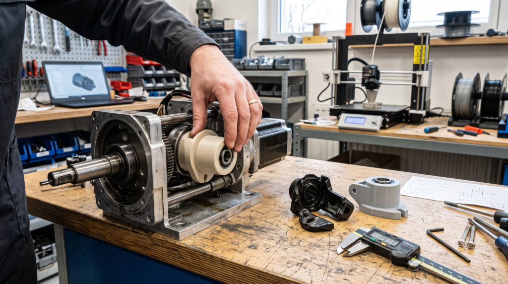
A replacement part can look perfect on the screen and still miss a screw hole, bind against a shaft, flex in the wrong direction, or sit slightly crooked after installation.
That does not automatically mean the project failed. It may mean the first print did exactly what a well-planned prototype was supposed to do: reveal what the digital model could not prove by itself.
Why does a 3D-printed replacement part need a test fit?
A test fit checks the features that control real-world function: overall size, hole location, alignment, clearance, movement, attachment, and contact with surrounding components. Even careful measurements cannot always predict how printer setup, material behavior, print orientation, first-layer compression, or an incomplete original part will affect the finished fit.
The smartest first prototype is often a controlled question—not an attempt to produce the prettiest possible final part.
When people picture custom 3D printing, they often imagine a direct path from measurement to CAD model to finished component. Sometimes a simple part works that way. A basic cap, spacer, or cover may fit correctly on the first attempt.
Custom replacement parts become less predictable when they include clips, mating curves, hidden contact points, moving features, precise hole spacing, damaged reference surfaces, or limited installation clearance.
In practical custom work, I would rather learn from one controlled test than pretend the first model contains certainty that the available measurements do not support.
A test print is not automatically a failed print
A print fails when it provides no useful result or when a preventable process problem ruins the intended test. A prototype that identifies a clearance problem, confirms two mounting holes, or reveals that a clip needs more flexibility has produced valuable information.
The distinction comes down to intent.
Unplanned miss
The complete part is printed without defining what needs to be verified. When it does not fit, several dimensions and settings are changed at once.
Controlled test
The uncertain interface is identified before printing. The prototype checks that feature, the result is measured, and one deliberate revision follows.
That second workflow turns prototyping into evidence. It also helps explain why custom-part pricing cannot be calculated from filament weight alone. The first part may carry measurement, modeling, setup, inspection, and revision work that later copies can share.
For a closer look at those cost factors, read How Much Does a Custom 3D-Printed Part Cost?
What a useful test fit should verify
A prototype should not be judged only by whether it can be pushed into place. A forced fit can hide an undersized opening, poor alignment, or stress that may crack the part later.
A useful evaluation moves through five checkpoints.
Envelope
Does the part occupy the available space without striking a cover, housing, cable, neighboring component, or moving surface?
Interfaces
Do screw holes, shafts, slots, shoulders, clips, tabs, mounting faces, and locating features line up with the real assembly?
Movement
Can the part slide, rotate, flex, open, close, or release without binding or scraping against nearby surfaces?
Retention
Does the part remain in place under its expected handling, or is the fit too loose, too tight, or dependent on excessive force?
Function
After installation, does the surrounding product operate as intended without creating a new obstruction, pinch point, misalignment, or weak connection?
Prototype-first versus final-first printing
A final-first approach tries to settle every design choice before physical evidence is available. A prototype-first approach concentrates effort on the features most likely to determine success.
| Decision | Final-First Approach | Controlled Test-Fit Approach |
|---|---|---|
| Geometry | Models the entire finished part immediately. | May isolate the uncertain holes, clip, curve, slot, or mounting surface. |
| Appearance | Adds texture, logos, fillets, and cosmetic matching before fit is proven. | Proves working geometry before spending time on visual refinement. |
| Material | May begin with the final material even when only geometry is being checked. | Uses a suitable low-risk prototype material when appropriate, followed by validation in the final material. |
| Quantity | Risks printing several unverified copies. | Verifies one controlled part before starting the batch. |
| Revision | May change several dimensions after an unclear result. | Records the result and adjusts one defined variable when possible. |
| Success test | Asks, “Does it look finished?” | Asks, “Did this print answer the question?” |
You may not need to print the entire part
A complete prototype makes sense when several surfaces interact or the part must be evaluated as one connected structure. However, printing the full geometry is not always the fastest way to test one uncertain feature.
Print a hole section
When screw or shaft fit is uncertain, a small coupon containing the hole can compare several diameters without printing the entire bracket.
Print the mounting face
A thin section can confirm hole spacing, edge clearance, alignment, and contact with the real assembly.
Print one clip
A partial model can test hook depth, insertion force, release behavior, and flex direction before the complete housing is produced.
Print the mating curve
A narrow contour sample can show whether a curved surface rocks, leaves a gap, or interferes with the object it must follow.
These smaller tests can reduce printing time and make the result easier to interpret. They also create a cleaner comparison when several controlled variations are placed in the same test piece.
Why exact-size CAD does not guarantee exact fit
A digital model describes the intended geometry. The physical print is also influenced by the printer, nozzle, extrusion behavior, first layer, material, cooling, orientation, supports, slicing choices, and the shape of the feature.
This is why a post modeled at the same nominal size as its mating hole may not slide into place. A moving connection, removable cover, press fit, locating pin, and freely rotating shaft do not require the same clearance or behavior.
There is no single clearance value that should be copied into every design. The intended type of fit and the actual printing process both matter.
Use a tolerance test as a starting point—not a universal promise
A clearance gauge can help show how a particular printer and setup handle closely spaced features. Maker’s Muse offers a clearance and tolerance gauge for readers who want to explore this principle.
The result should still be confirmed using the intended material, orientation, feature shape, and real assembly. A vertical round hole may not behave exactly like a horizontal hole, deep slot, snap feature, or curved mating surface.
How the P.R.I.N.T. Method™ controls the revision
Test fitting works best when it remains connected to the part’s actual job. The 3D Printing by Kevin P.R.I.N.T. Method™ keeps the project from turning into random dimensional guessing.
The important phrase is revise deliberately. When a hole, wall, clip, and overall scale are all changed after one test, it becomes difficult to know which adjustment solved the problem—or created the next one.
A practical test-fit workflow
- Name the uncertainty. Decide whether the main question involves hole spacing, clearance, flex, alignment, overall size, a mating curve, or another specific interface.
- Choose a stable reference. Measure from a flat mounting surface, centerline, undamaged shoulder, or other dependable feature rather than stacking several uncertain dimensions.
- Print the smallest useful test. Isolate the uncertain geometry when possible. Use the complete part only when the full structure is needed to evaluate the fit.
- Inspect before installation. Check for warping, first-layer spread, poor hole quality, delamination, support damage, or another printing defect that could distort the result.
- Test without forcing the part. Fit should be evaluated carefully. Excessive pressure can damage the prototype, mating component, fastener, or surrounding equipment.
- Record the result. Note where the part contacts, how far it moves, which holes align, how much looseness is present, and what force is required.
- Change one defined variable. Revise the dimension most strongly connected to the observed problem instead of making a broad collection of unrelated adjustments.
- Validate the final configuration. Confirm the chosen material, orientation, geometry, fasteners, inserts, finishing, and expected operating conditions before producing additional copies.
The final material may require another check
A quick prototype can verify basic geometry, but the final material may print, flex, shrink, bridge, cool, or respond to fasteners differently.
A PLA test may answer whether two holes line up. It does not automatically prove that the final PETG, ASA, nylon, or other selected material will provide the required fit and behavior under use.
The final validation becomes especially important when the part depends on:
- Snap-fit flexibility or repeated bending
- Threaded inserts or self-tapping screws
- Heat, sunlight, moisture, or vehicle exposure
- Long-term clamping or sustained load
- Impact or vibration
- Multiple parts that must assemble consistently
Geometry can be proven in stages, but the final part should still be evaluated in the configuration that will actually be used.
Test fitting must not create a safety hazard
Shut down and isolate equipment before placing hands, tools, or prototypes near moving mechanisms, electrical components, fans, belts, gears, hot surfaces, or pinch points.
A desktop FDM replacement should not be treated as an automatic substitute for safety guards, pressure components, medical parts, certified food-contact parts, critical vehicle components, life-supporting hardware, or structures whose failure could injure someone or cause major damage.
Sometimes the correct result of a project review is to use an original replacement, another manufacturing process, professional engineering evaluation, or no custom part at all.
When is the first prototype ready to become the final part?
A prototype is ready to move forward when the important interfaces have been verified and the remaining decisions are understood.
Fit is confirmed
Mounting faces sit correctly, holes align, required gaps remain, and the part does not need to be forced into position.
Movement is confirmed
Sliding, rotation, flexing, opening, closing, or release occurs without binding or unwanted contact.
Requirements are confirmed
Material, heat exposure, load, weather, appearance, quantity, and expected lifespan have been addressed.
Risk is acceptable
The application is suitable for the chosen process, and failure would not create an unacceptable safety or equipment hazard.
Why one verified part matters before a small batch
Printing ten copies does not make uncertain geometry more accurate. It multiplies the result.
Before a small production run, the first completed part should verify more than basic dimensions. It may also need inspection for support marks, fastener installation, assembly sequence, packaging needs, label placement, and consistency with the customer’s actual use.
Once the design and workflow are proven, the project can move from development into repeat production with far less uncertainty. This is one reason the first part may represent more work than the copies that follow.
What should you send for a replacement-part test-fit project?
You do not need to arrive with a finished engineering drawing. A useful starting packet can include:
- The broken part and every surviving fragment
- Clear photographs from several directions
- A wide photograph showing where the part belongs
- Overall dimensions and critical hole or slot spacing
- Photographs of the mating component
- A description of how the part attaches and moves
- Expected heat, sunlight, moisture, load, vibration, or flexing
- The desired quantity
- Any available STL, STEP, OBJ, sketch, drawing, or PDF
The guide How to Measure a Part for 3D Printing explains how to collect these details without pretending every surface must be measured with laboratory precision.
It is also worth checking Should You 3D Print or Replace a Broken Plastic Part? before investing time in a custom solution. A readily available original component may still be the simplest and most economical answer.
Build your complete practical 3D-printing workflow
P.R.I.N.T. It: Practical 3D Printing for Beginners is a 40-page digital guide covering printer choice, workspace setup, slicers, materials, calibration, first prints, troubleshooting, replacement-part planning, maintenance, and practical customer work.
It is built for readers who want to move beyond random prints and understand how useful parts are planned, tested, and improved.
Explore the Practical EbookQuick knowledge check
Open each question to check the most important ideas from this guide.
1. Does a prototype that does not fit perfectly always count as a failed print?
No. A controlled prototype can be successful when it clearly identifies a dimensional, clearance, movement, alignment, or attachment issue that guides the next revision.
2. Why might you print only one section of the replacement part?
A smaller section can test an uncertain hole, clip, curve, slot, or mounting face faster and with less material than printing the entire design.
3. Why should you avoid changing several unrelated dimensions after one test?
Changing several variables makes it difficult to determine which adjustment solved the original problem or caused a new one. Controlled revisions produce clearer evidence.
4. Does a successful PLA geometry test prove that every final material will behave identically?
No. The final material, orientation, fasteners, inserts, load, heat exposure, and operating conditions may require additional validation.
Frequently asked questions
How many test prints does a custom replacement part need?
There is no fixed number. A simple part with complete measurements may work on the first print. A damaged component with hidden geometry, clips, moving features, or several mating surfaces may require controlled revisions. The objective is not to reach an arbitrary prototype count; it is to resolve the important uncertainties efficiently.
Can the first prototype use inexpensive material?
Sometimes. A suitable prototype material may verify basic dimensions and alignment. However, the final material may behave differently, so critical fit, flex, fastener, heat, load, and environmental requirements should be validated in the final configuration.
Should a test-fit part be forced into place?
No. Excessive force can damage the printed part, hide a dimensional error, stress the mating component, or create an unsafe condition. Record where contact occurs and revise the appropriate geometry.
Can sanding or filing replace a CAD revision?
Light finishing may be appropriate for removing a support mark, burr, or minor surface irregularity. Repeatedly removing substantial material to make a part fit may indicate that the model, clearance, orientation, or printing process should be corrected—especially when more than one copy is needed.
Why does the first custom part sometimes cost more than later copies?
The first part may include measurement, reverse engineering, CAD development, material decisions, printer setup, prototypes, fit checks, revisions, and verification. Later copies can share the proven design and workflow, although each still requires material, machine time, inspection, cleanup, and handling.
Can photographs alone prove that a replacement part will fit?
Photographs provide valuable context but may not reveal depth, exact scale, hidden features, wall thickness, hole spacing, or required clearance. Useful dimensions, the mating assembly, and a controlled test fit often remain necessary.
When replacement parts disappear, we make the next one.
Send the broken component, photographs, measurements, quantity, operating conditions, and any available digital files. The project review will focus on the simplest practical path—including whether a controlled test fit should come before the final part.
