
The mounting holes line up. The replacement slides into place. For a moment, it looks like the problem is solved—until a tab snaps during installation or the bracket cracks when you start using it.
That is frustrating, but the broken part can still teach you something useful. Before printing another copy, separate two questions: Did it fit correctly, and did it handle the job?
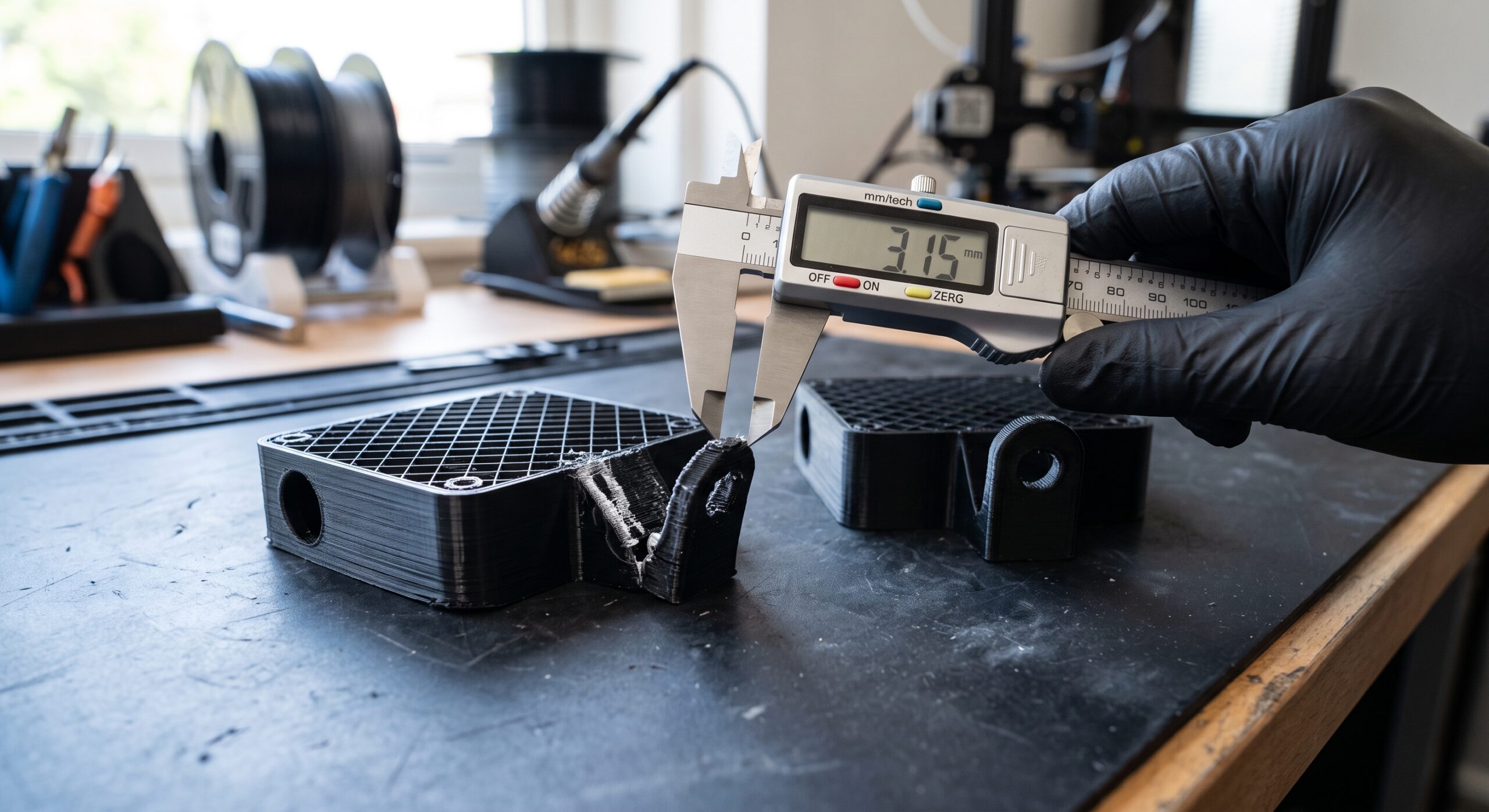
Quick answer: What should you check first?
If your 3D-printed part fits but breaks, photograph the failure before changing settings. Note where the crack started, how the part was installed, and what force it experienced.
Then review layer direction, the geometry and printed walls at that location, and whether the material suits the environment.
Change one main variable for the next comparison. More infill can be useful, but it is not a universal fix.
1. Read the broken part before you reprint it
Keep both pieces and take clear photographs of the break, the installed position, and the surrounding hardware. Record whether failure happened while pushing the part into place, tightening a screw, or using it afterward.
Look for a repeatable location: the base of a tab, the edge of a hole, a thin neck, or a seam between printed layers. Treat that location as a clue rather than a complete diagnosis.
- Installation failure: Check whether the part needed excessive force, an opening was too tight, or a fastener was tightened beyond the intended assembly condition.
- Failure during use: Record the direction of movement, the supported item, and anything that changed before the break.
- Similar failures across copies: Compare the model revision and print setup before assuming every copy needs a different material.
A useful note is specific: “The tab broke at its base while snapping over the desk edge.” “Weak print” leaves too many possibilities open.
2. Compare layer direction with the way the part is used
FDM printing builds a part layer by layer. The model’s orientation affects its mechanical behavior, so the easiest position to print deserves a second look when a functional part fails.
In the slicer, inspect the damaged feature in its original orientation and one practical alternative. Ask whether the new position changes the way printed layers run through the feature.
Also check whether it introduces supports on a surface that needs to fit accurately.
There is no universal “strongest angle” for every bracket or clip. Prusa’s design guidance explains why orientation and geometry belong in the same review.
3. Check the actual walls at the failure point
Perimeters are the paths that form printed walls. They are a meaningful strength setting to inspect before treating infill percentage as the whole answer; see Prusa’s explanation of layers and perimeters.
Zoom into the sliced preview at the broken tab or neck. Does the feature contain the paths you expected? Does a small section become much narrower than the surrounding part?
For example, a roomy bracket body may allow several walls while its tiny connecting tab remains narrow. Adding interior density to the body does not automatically change that tab’s geometry.
If you revise the CAD model, preserve the mating dimensions that already work. Start with the part measurement guide and identify which surfaces must stay fixed.
4. Revisit the job requirements before changing filament
Write down the conditions the part actually faces: warmth, sunlight, moisture, repeated movement, impact, or a steady force. Material selection should follow those requirements.
Use the manufacturer’s information for the exact filament grade as a starting point. A material name alone cannot establish how your finished design will behave.
Also consider the consequence of failure. A desk cable guide offers a different testing opportunity from a component that protects someone or carries a critical load.
High-consequence parts need an appropriate engineering and validation process.
5. Make the next print answer one question
For a low-risk comparison, choose a repeatable check and write down what would count as a useful result before printing. Keep the original file and settings so you can compare the revision with the baseline.
You might compare two orientations of the same model, or compare one geometry revision in the original orientation. Changing geometry, material, walls, and temperature together makes it harder to identify what helped.
A small feature sample can answer a narrow fit or printability question. It cannot establish the strength of the complete assembly. Return to the full part when checking its intended function.
| What you observed | Useful next check | What it does not prove |
|---|---|---|
| Break during assembly | Compare clearance and installation method | Long-term durability |
| Crack follows a layer boundary | Review print quality and compare a practical orientation | That orientation is the only cause |
| Same narrow feature breaks repeatedly | Inspect its geometry and sliced paths | That denser body infill will repair it |
| Failure follows a change in environment | Review conditions and exact material data | Suitability from a material label alone |
Use the P.R.I.N.T. Method™ to organize the revision
Add a failure-review entry to your project planner. Keep it with the photos, model revision, and slicer project so the next attempt has a clear purpose.
- Problem: Describe what failed and when.
- Requirements: Record the real use and acceptable outcome.
- Interfaces: Preserve the fit dimensions that worked; check assembly clearance.
- Next-Best Materials & Methods: Choose the next comparison based on the evidence.
- Test & Tune: Record what changed, what happened, and what remains untested.
For a reusable planning reference, explore P.R.I.N.T. It: Practical 3D Printing for Beginners, which includes project planners and a fillable worksheet.
Four-question knowledge check
Choose an answer, then tap to reveal the explanation.
1. A replacement fits correctly. What have you established?
- It is safe for every use.
- Its checked interfaces fit.
- Its material is ideal.
Reveal answer 1
B. Its checked interfaces fit. Fit is valuable evidence, but function and durability need their own evaluation.
2. A tab breaks during installation. What is the most useful first step?
- Document the break and assembly conditions.
- Set every model to 100% infill.
- Order a new printer.
Reveal answer 2
A. Document the break and assembly conditions. The failure location and installation conditions help choose a relevant next check.
3. Which comparison is easier to interpret?
- Change five settings and the filament.
- Print an unrelated model.
- Compare one planned change with the recorded baseline.
Reveal answer 3
C. Compare one planned change with the recorded baseline. A controlled comparison helps connect the result to the variable you changed.
4. A small opening sample fits. What should happen next?
- Approve every application.
- Check the complete part for its intended function.
- Discard the test record.
Reveal answer 4
B. Check the complete part for its intended function. A small sample answers a limited question. The full assembly still needs evaluation.
Frequently asked questions
Will 100% infill stop my part from breaking?
It may help some designs, but it does not address every cause. Review the failure location, geometry, printed walls, orientation, and use before selecting the next change.
Should I change material or orientation first?
Choose based on the evidence. An unsuitable environment makes material review important; a failure associated with layer direction may justify an orientation comparison. Record a baseline and avoid changing everything together.
Can I make a broken tab thicker?
Possibly, if the mating space and required movement allow it. Check the revised fit and behavior rather than assuming a thicker feature will still assemble correctly.
Can Kevin review a replacement that keeps breaking?
Use the project intake form to share the intended use, photos, dimensions, quantity, available files, and failure details. Review determines the practical next step; submitting a request does not guarantee acceptance.
Before you print another copy
Keep the broken part, label the file, and write down the next question. That gives your revision a purpose—and makes the result more useful even if another adjustment is needed.
What part has surprised you by fitting perfectly and then failing? Share where it broke and what it was doing in the comments. Send private project files through the intake form.
Fact-checked October 5, 2026: General guidance reviewed against the linked Prusa documentation and current 3D Printing by Kevin resources. The examples are illustrative; this article reports no measured strength results and does not certify a part for service.
