
The CAD model looked perfect.
Every hole was where it belonged. Every edge lined up. The measurements looked right.
Then the print came off the bed.
One mounting hole was just far enough off to ruin the fit. The clip was too stiff. And the part that looked completely reasonable on the screen suddenly made one thing very clear:
The computer had approved it.
The real world had not.
That is the part of 3D printing people do not talk about enough.
Designing the model is only half the job.
The other half begins when that model becomes a physical object you can hold, bend, bolt down, snap into place, drop, load, heat, test—and occasionally stare at while wondering how something that looked so right went so wrong.
This is how I move a project from idea to CAD to prototype to a part that actually works.
Quick Answer
A successful 3D print starts long before the printer moves. Define what the part must do, protect the critical dimensions, design around real-world clearances and forces, choose material and orientation deliberately, inspect the sliced model, and test the risky features before committing to the final print.
The Printer Is Usually the Least Interesting Part
People love talking about printers.
Speed. Acceleration. Build volume. Nozzle temperature. Input shaping. Multicolor systems.
All useful.
But when I am trying to create a functional part, my first question is not:
Which printer should I use?
It is:
What is this thing supposed to survive?
Suppose I am replacing a cracked mounting bracket.
I want to know what it holds.
I want to know where the force is coming from.
I want to know whether it lives in a hot car, under a cabinet, beside a motor, outside in the sun, or on something that gets slammed shut three times a day.
I want to know whether it needs to flex.
And I definitely want to know what happens if it fails.
Those answers determine the design.
The printer comes later.
A Good-Looking Model Can Still Be a Bad Part
This is one of the traps of CAD.
CAD is clean.
The physical world is not.
In CAD, surfaces touch perfectly.
In the real world, printed plastic expands, holes print undersized, corners bulge, screws need room, and assemblies need clearance.
A model can be mathematically beautiful and mechanically useless.
That is why I think about the part as a working object, not just a shape.
The P.R.I.N.T. Method Keeps Me From Designing Blind
Before I start chasing dimensions, I like to frame the job with the same five questions.
P — Problem
What is actually broken, missing, inconvenient, or impossible to buy?
R — Requirements
How strong, accurate, flexible, heat-resistant, durable, or attractive does it need to be?
I — Interfaces
Where does it bolt, snap, slide, clamp, rotate, rest, or mate with something else?
N — Next-Best Materials & Methods
What material, print orientation, manufacturing approach, and construction method make sense?
T — Test & Tune
What should the first print prove before I spend more time and material?
That last question saves a lot of headaches.
You do not need the first print to be perfect.
You need it to expose the lie.
The wrong clearance.
The weak tab.
The hole that looked right but is not.
The feature you could not measure accurately until the part was in your hand.
That is useful information.
Some of the Best Projects Start With Almost Nothing
You do not need a polished CAD file to begin.
Sometimes the whole project starts with a sentence:
“This piece broke and nobody sells it anymore.”
Or:
“I need something that holds this here.”
Or my favorite kind of challenge:
“I know what I need. I just don’t think it exists.”
That is enough to start asking questions.
| You Have | What It Tells Me | What Happens Next |
|---|---|---|
| An idea | The job the part needs to do | Define dimensions and constraints |
| A broken part | How the original was shaped and mounted | Measure the important interfaces |
| A 3D scan | Complex surface geometry | Clean, verify, and rebuild where needed |
| An STL or 3MF | A printable mesh | Check scale, fit, and manufacturability |
| A STEP file | Editable CAD geometry | Review how it will behave when printed |
Step 1: Find the Dimensions That Can Ruin the Entire Job
Every part has dimensions that matter.
And then it has dimensions that really matter.
If a decorative corner changes by 0.4 mm, nobody may notice.
If a bolt hole moves by 0.4 mm, the part may be worthless.
That difference matters.
When I am modeling a functional part, I pay special attention to:
- Screw holes
- Bolt spacing
- Shaft diameters
- Tabs and snap fits
- Mounting faces
- Slots and channels
- Hinges
- Clearance around moving parts
- Surfaces that must sit flush
Those are the features that decide whether you say:
“Nice print.”
Or:
“It fits.”
I care much more about the second one.
Sometimes Copying the Original Is the Wrong Move
Here is where replacement-part design gets fun.
If the old part snapped at the same thin corner it was molded with twenty years ago, why would I automatically reproduce that weak spot?
I may be able to improve it.
Add a fillet.
Thicken a boss.
Change the wall transition.
Move stress away from a sharp corner.
Reorient the part so the layers carry the load differently.
Keep the mounting dimensions identical while changing everything around them that does not need to stay identical.
That is when 3D printing becomes more than duplication.
It becomes a chance to make version two.
Step 2: Design for the Hand Holding the Part, Not the Screen Showing It
I have spent years working in 3D modeling and Shapr3D, and CAD has taught me something slightly annoying:
It will happily let you design something that is impossible to install.
You can build a beautiful enclosure and forget that a screwdriver cannot reach the screws.
You can make two surfaces fit perfectly and forget that printed parts need clearance.
You can design a great clip and orient it so the layer lines run exactly where the clip wants to break.
So before I call a model finished, I am asking:
- Can I actually assemble it?
- Can I reach the fasteners?
- Do mating parts have clearance?
- Are the walls thick enough to print reliably?
- Will the important surfaces need support?
- Where will the layer lines run?
- Will stress hit a weak feature?
- What happens when someone installs it slightly crooked?
That is the difference between designing geometry and designing a part.
See Shapr3D’s current export documentation.
Step 3: A 3D Scanner Is Powerful—But It Is Not a Magic Copier
Scanning can save enormous amounts of modeling time.
It is especially useful when you are dealing with curves, contours, sculptures, housings, handles, and other shapes that are miserable to measure with calipers.
But a scan can also give you a beautifully detailed mess.
Noise.
Holes.
Missing surfaces.
Glare artifacts.
Extra background geometry.
Features that look close but are not accurate enough to control a mechanical fit.
So I treat scanning as a tool, not a shortcut to certainty.
I may scan the overall shape and then rebuild the screw holes, mounting surfaces, tabs, and other important features as clean CAD geometry.
That combination can be far more useful than blindly printing the raw mesh.
See the current 3DMakerpro scanner lineup.
Affiliate disclosure: Some links in this article are affiliate links. If you purchase through them, I may earn a commission at no extra cost to you.
Step 4: “Just Print It in PLA” Is Not a Material Strategy
PLA is great.
Until it is not.
A part sitting on a shelf indoors has one job.
A clip flexing open fifty times a week has another.
A dashboard bracket baking inside a closed car in July has another.
An outdoor fixture dealing with UV and rain has another.
Material choice follows the environment.
| If the Part Will… | I Start Asking… |
|---|---|
| Get hot | Will the material soften or creep? |
| Live outside | How will it handle UV, rain, and temperature swings? |
| Flex repeatedly | Does the material tolerate repeated bending? |
| Carry load | Which direction will the force act? |
| Be visible | Does surface finish matter as much as strength? |
PLA, PETG, ABS, ASA, TPU, and other materials all have strengths and weaknesses.
The question is not:
“Which one is strongest?”
The better question is:
“Which one fails the least badly in this job?”
Step 5: Rotate the Model 90 Degrees and You May Have Designed a Different Part
This still catches people.
Orientation is not just about getting a model to fit on the build plate.
Turn the part and you may change:
- Where the layer bonds take stress
- How strong a tab becomes
- Whether a hole prints cleanly
- Which face looks best
- How much support is needed
- How long the print takes
That means a part can be strong in one direction and surprisingly weak in another.
If a clip keeps snapping across the layer lines, pouring more infill into the model may be the wrong answer.
Rotate it.
Redesign it.
Change the wall strategy.
Make the force travel through the part differently.
Kevin’s Workshop Note
When a part breaks, look at the break before changing the slicer. The fracture usually tells a story. If the crack follows the layers, orientation may be shouting louder than infill.
Step 6: The Slicer Preview Is Where Cheap Mistakes Go to Die
Or at least they should.
Once the machine starts printing, every mistake starts costing filament and time.
Before that, the slicer is still giving you one last chance to catch something stupid.
I look for:
- Walls that vanish
- Unsupported islands
- Giant support forests
- Odd gaps
- Wrong scale
- Bad first-layer contact
- Incorrect material profiles
- A print time that suddenly doubled for no obvious reason
A five-minute preview can save a six-hour print.
That is a trade I will take every time.
Step 7: Do Not Print the Whole Thing Just to Discover One Hole Is Wrong
This is one of the best habits I have picked up.
If I am uncertain about one section, I print that section.
Not the whole housing.
Not the entire bracket.
Not twelve copies.
Just the feature that can ruin the job.
Maybe I need to test:
- A mounting hole
- A snap tab
- A shaft fit
- A clearance gap
- A hinge
- A mating surface
Print the risky feature.
Put it where it belongs.
See what reality says.
If it fits, move forward.
If it does not, change the model.
Either way, you learned something for the price of a small test print.
That is not wasted filament.
That is cheap information.
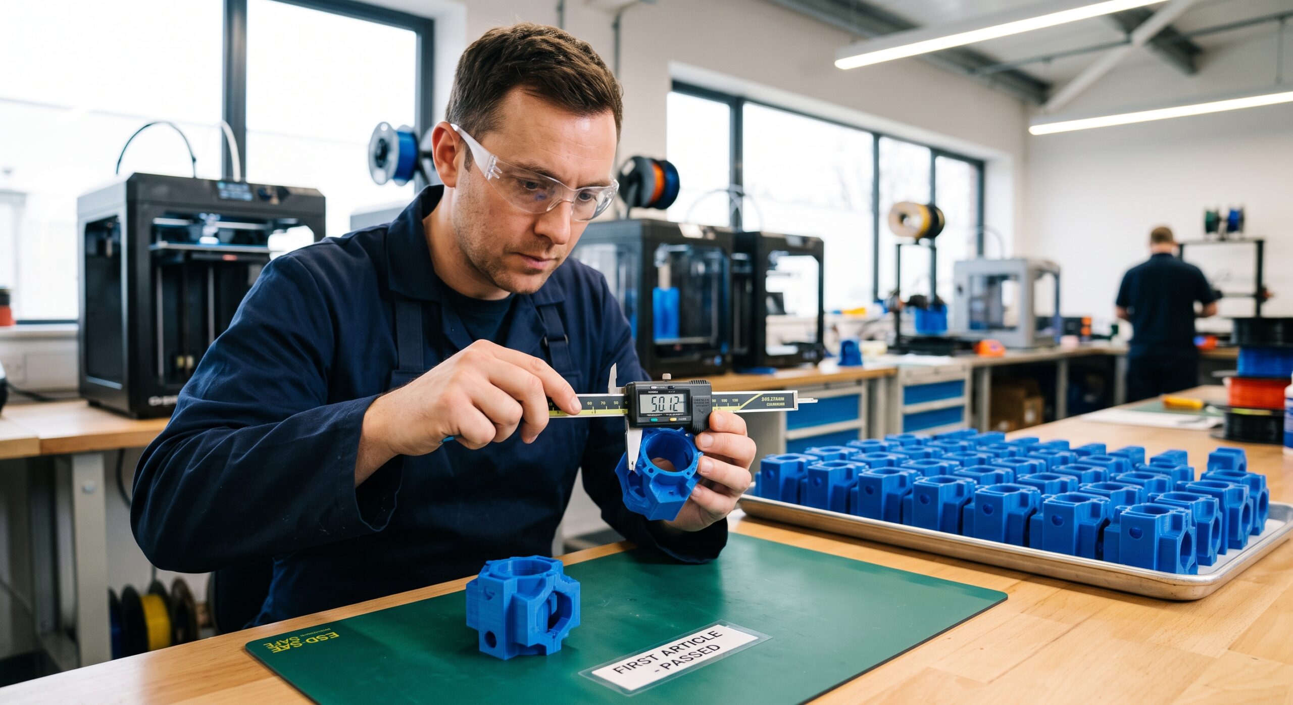
This Is the Moment the Image Matters
The photo above is the part of the process I trust most.
The CAD says the dimension is right.
The slicer says the file is printable.
The printer says it completed the job.
Fine.
Now measure the physical part.
Fit it.
Use it.
Push on it.
Make sure the production sample deserves to become a production batch.
Because printing twenty perfect copies of the wrong part is still printing twenty wrong parts.
A Prototype Is Not Supposed to Protect Your Feelings
Its job is to expose problems.
If the mounting tab needs 0.4 mm more clearance, good.
Now you know.
If the wall flexes too much, good.
Now you know.
If the part fits but cannot be installed because another component blocks access, that is frustrating—but still useful.
The prototype told you the truth before the final version did.
That is exactly what you paid it to do.
The Design-to-Print Reality Check
What must this part do?
If you cannot explain the job in one sentence, the design probably is not ready.
Which dimensions can ruin the fit?
Mark them before you start chasing cosmetic details.
Where will the part live?
Heat, UV, moisture, movement, vibration, and chemicals all matter.
Where will the force travel?
That answer should influence geometry and orientation.
What am I least certain about?
Print that part first.
What does success look like?
Know what the prototype needs to prove before you press Print.
You Can Start With a Sketch, a Broken Part, or a Sentence
You do not have to show up with a polished engineering package.
A project can start with:
- A broken original part
- A hand sketch
- Photos
- Measurements
- An STL
- A STEP file
- A scan
- An explanation of the problem
Sometimes all I need to begin is enough information to answer one question:
Is there a practical path from this problem to a printed solution?
Start a 3D printing project review →
If You Send Me a File, Tell Me What the File Cannot Tell Me
A CAD file shows geometry.
It does not tell me why the geometry matters.
So if you already designed the part, tell me:
- What it does
- Where it installs
- Which dimensions matter most
- What it connects to
- What material you were considering
- Whether it has already been printed
- How many you need
That context can completely change how I approach the print.
Should You Learn to Do All of This Yourself?
If you like mechanical puzzles, CAD, troubleshooting, failed prints, late-night slicer experiments, and the occasional victory dance when a stubborn part finally clicks into place, absolutely.
3D printing is ridiculously satisfying when the process itself is part of the fun.
My 3D Printing for Absolute Beginners guide is a good place to start.
You can also go deeper with P.R.I.N.T. It: Practical 3D Printing for Beginners.
But if all you want is one replacement clip, one prototype, a custom fixture, or a small batch of parts, you do not need to become a printer mechanic first.
Sometimes you just need the part.
Quick Knowledge Check
1. What matters more at the beginning: printer speed or understanding the job?
Understanding the job. The environment, load, fit, and function should guide the design and manufacturing decisions.
2. Is a 3D scan automatically a production-ready model?
No. Scans can be extremely useful, but critical mechanical features often need cleanup, dimensional verification, or CAD reconstruction.
3. Why should you sometimes print only part of the model?
A small test can verify the feature most likely to cause failure before you spend time and material on the entire part.
4. Is a prototype that reveals a problem a failure?
No. A prototype that exposes a problem has done its job. It turned uncertainty into information.
Frequently Asked Questions
Why does a CAD model sometimes fit poorly after printing?
Because CAD geometry is exact and physical printing is not. Printer calibration, tolerances, material behavior, hole geometry, orientation, and first-layer effects can all change the finished dimensions.
Can a broken plastic part be recreated?
Often, yes. Even a damaged original can provide useful dimensions, mounting points, wall thicknesses, curves, and clues about why the original failed.
Do I need a STEP file?
Not always. STL and 3MF files are commonly used for slicing, while STEP files can be especially useful when dimensional editing or design changes are needed.
Can you work from just photos and measurements?
Sometimes. Clear photos, a few reliable measurements, and information about how the part fits into the surrounding assembly can be enough to begin evaluating the project.
Can a replacement part be stronger than the original?
Potentially. A replacement may allow changes to wall thickness, fillets, geometry, material, or print orientation while preserving the dimensions required for fit.
Can Kevin help if I do not know CAD?
Possibly. You can start with a broken part, sketch, photos, measurements, scan, or explanation of the problem and use the project intake form to see whether the job is a practical fit.
The Best Moment Happens After the Printer Stops
I still like watching a print start.
I like seeing the first layer go down clean.
I like watching a shape slowly appear where there was nothing a few hours earlier.
But that is not my favorite part.
My favorite part happens after the printer stops.
You remove the piece.
You clean it up.
You carry it over to the machine, cabinet, bracket, fixture, appliance, or whatever started the whole problem.
You line it up.
You push it into place.
And it fits.
Not because the CAD looked good.
Not because the printer was fast.
Not because the filament box said “engineering grade.”
It works because every decision before that moment was aimed at one thing:
making the physical part solve the real problem.
Have something you cannot buy anymore—or something that never existed in the first place?
Send the broken part, sketch, measurements, photos, scan, or 3D file. I can look at what you have and help determine whether there is a practical path to a working printed part.
What are you trying to make? Tell me about it in the comments. The projects that start with “I don’t think anyone makes this” are usually the ones I enjoy hearing about most.
