
Practical FDM troubleshooting
The print finished. The walls still looked rough. The change that helped was slowing the outer walls—the surfaces I would see, handle, and inspect.
I had already tried temperature changes, belt checks, different filament, and bed calibration. What finally helped those prints was giving the visible surfaces a more controlled speed.
Here is how to test the same idea on your printer, what to keep unchanged, and how to recognize a problem that needs a different fix.
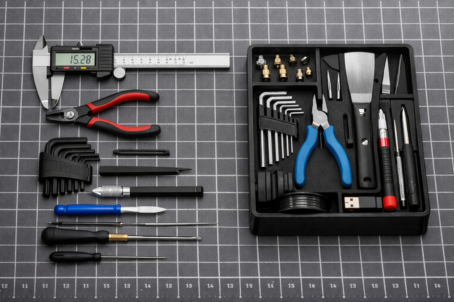
Why the outer walls made the difference
My parts were staying on the bed and finishing without a dramatic failure. The disappointment appeared afterward: faint waves, softened details, and patches that reflected light differently.
Outer walls form the visible boundary of a printed part. Slowing that feature can change its surface finish while allowing inner walls and infill to retain their existing speeds. OrcaSlicer documents separate speeds for these features, including a separate top-surface setting.
The improvement in my prints gave me a better way to think about a slicer profile: assign speed according to the job each feature performs. A visible enclosure wall and the material inside it do not necessarily need the same treatment.
One setting. Two comparable samples.
80 mm/s
Use your existing outer-wall speed and save the original profile.
45 mm/s
Change the outer-wall speed. Hold the other settings steady.
Match the symptom before changing the speed
“Looks terrible” is a starting point, but a useful diagnosis needs a location and a pattern. Look at whether the defect follows a corner, appears across the entire wall, or affects only the top.
| What you see | What to investigate | Useful next step |
|---|---|---|
| Echoes after corners or lettering | Ringing from motion and vibration | Check the mechanics, then compare outer-wall speed; test acceleration separately. |
| Fine, regularly spaced vertical lines | Speed-dependent motor or motion artifacts | Compare several speeds; the lowest speed may not give the best finish. |
| Gaps that worsen in fast sections | Extrusion delivery or melt-flow limits | Inspect the nozzle and filament path; review volumetric flow in the slicer. |
| Popping, bubbles, and rough extrusion | Moisture or another extrusion problem | Check filament condition and the manufacturer’s drying guidance. |
| Rough top with acceptable side walls | Top-surface settings, flow, or insufficient support beneath the top | Troubleshoot the top separately before changing a good wall profile. |
| A raised line at the layer starts | Seam placement and extrusion transitions | Inspect seam settings and pressure/flow calibration. |
Technical references: Klipper on ringing, OrcaSlicer’s VFA test, Prusa on filament drying, and Prusa on seams.
If the part is lifting, shifting layers, or struggling to extrude at ordinary speeds, work through my 3D printing troubleshooting guide before treating this as a surface-speed problem.
Find the outer-wall setting in your slicer
Search the settings panel for outer wall or external perimeters. You may need Advanced or Expert visibility. Labels and panel arrangements vary by slicer version.
| Slicer | Setting to look for | Keep distinct from |
|---|---|---|
| Bambu Studio / OrcaSlicer | Outer wall, under Speed | Inner wall, top surface, and outer-wall acceleration |
| PrusaSlicer | External perimeters, under Print Settings → Speed | Perimeters and small perimeters |
| UltiMaker Cura | Outer Wall Speed, under Speed | Wall Speed and Inner Wall Speed |
For a conservative test with ordinary PLA, a 0.4 mm nozzle, and roughly 0.20 mm layers, 30–50 mm/s is a range worth investigating if your current outer walls are substantially faster. It is a test range from this workflow, not a manufacturer specification.
A well-tuned printer can make excellent surfaces above that range. If you already print at 35 mm/s, choosing 45 mm/s is an increase; diagnose the defect before copying the example.
Need a dependable starting profile before you compare? My go-to settings guide explains the broader setup.
Run a comparison that tells you something
Choose a small model that reproduces the problem: a straight wall, a corner, and a little raised or recessed text work well. Make the wall long enough for speed differences to appear; a tiny feature may be slowed by acceleration or cooling limits in both versions.
- Save the baseline. Duplicate the current profile and name the copy for this test.
- Print sample A. Record the outer-wall speed, material, nozzle, layer height, and actual duration.
- Change only outer-wall speed for B. For example, test 45 mm/s against an 80 mm/s baseline. Keep the same spool, orientation, bed position, and printer speed mode.
- Inspect both sliced previews. Look at speed and volumetric flow. Confirm that the relevant wall paths receive different speeds. Leave cooling safeguards enabled.
- Print B as a separate job. Use the same conditions as closely as practical. Keep automatic calibration choices consistent and record any change you cannot control.
- Compare after both parts cool. Use the same light, distance, and viewing angle. Inspect the same corner and lettering; measure the same fit-critical feature.
Setting 80 mm/s does not guarantee that the nozzle reaches it. Flow caps and cooling rules can lower the sliced speed, and short moves may not reach the requested speed during acceleration. Prusa explains how these speed limits interact.
If both samples look the same, check whether you actually tested different wall speeds. If B looks worse, restore A and investigate the pattern instead of assuming another slowdown must help.
If slower walls help only a little, check these next
Ringing: separate speed from acceleration
Speed describes how fast the head moves; acceleration describes how quickly that movement changes. A low wall-speed setting can still be paired with aggressive acceleration.
Check for loose parts and follow the printer maker’s belt-tension procedure. If the mechanics are sound, try a separate comparison with lower outer-wall acceleration, within your machine’s supported settings. OrcaSlicer provides feature-specific acceleration controls.
On supported printers, properly calibrated input shaping can reduce ringing. Use your printer’s procedure; Klipper’s documentation explains both the vibration problem and the tradeoff between compensation and detail smoothing.
Fine vertical lines: compare a range of speeds
Some motor-related surface patterns become more visible within particular speed bands. Continually slowing the printer can move you into one of those bands. The OrcaSlicer VFA calibration guide describes a speed test for finding where these artifacts appear.
Gloss changes: inspect speed and cooling together
A glossy patch beside a dull one can reflect changes in printing conditions. Check whether the change starts where the slicer slows an overhang or a short layer. Bambu Lab’s guide to variations in print gloss addresses this pattern.
Keep material-appropriate cooling enabled. If the wall-speed change reveals a need for a temperature adjustment, make that a separate test within the filament maker’s range.
Extrusion gaps: check how much plastic the hotend must deliver
Wider lines and taller layers demand more material at the same printing speed. A useful rough estimate is:
The material demand behind the speed
Approximate width of the deposited line
Height of the current printed layer
Speed along that extrusion path
0.45 × 0.20 × 80 ≈ 7.2 mm³/s
A correctly calibrated maximum volumetric speed caps excessive extrusion demand. Review the slicer’s flow preview and Prusa’s explanation of volumetric speed. Raising the flow percentage globally is not a substitute for resolving a delivery limit.
If extrusion is inconsistent even at modest speeds, check the filament path and nozzle. Popping or bubbles also warrant checking moisture; follow the material and spool manufacturer’s drying limits. Prusa’s drying guide explains why wet filament can undermine print quality.
Put the test into your P.R.I.N.T. planner
A useful profile needs a reason behind it. Apply the P.R.I.N.T. Method™ to this one surface-quality problem, then record the outcome beside your other project notes.
- Problem
- Name the defect and where it appears: for example, ripples after lettering on the front wall.
- Requirements
- Set the acceptable finish, fit, and print time before comparing samples.
- Interfaces
- Choose the hole, mating face, clip, or dimension you will measure after printing.
- Next-Best Materials & Methods
- Keep the current suitable material and orientation; test one targeted profile adjustment.
- Test & Tune
- Compare A and B. Keep, revise, or reject the change based on finish, fit, and time.
Your outer-wall test record
Fill in the fields, then save or copy your notes before leaving this page. Entries are not automatically saved or submitted.
For the wider workflow, see my practical 3D printing ebook and P.R.I.N.T. Method guide.
Four-question knowledge check
Choose an answer before opening each explanation. Give yourself one point for each correct answer.
1. Which first comparison best tests outer-wall speed?
- Change temperature, acceleration, and wall speed together.
- Print the same model again with only outer-wall speed changed.
- Compare two unrelated models made from different filament.
Reveal answer 1
B. Keeping the model and other settings consistent makes the result easier to interpret. Check the sliced preview to confirm that the relevant wall speeds actually differ.
2. The walls look good, but the top is rough. What should you do next?
- Diagnose top-surface flow, support, and speed separately.
- Assume the outer-wall speed must be wrong.
- Double every speed setting.
Reveal answer 2
A. Different features use different settings. Preserve the successful wall profile while investigating the top.
3. Fine vertical lines become worse after a slowdown. What does that suggest?
- The print must always be slowed further.
- The printer needs 100% infill.
- A speed-dependent artifact may need a range-of-speeds test.
Reveal answer 3
C. Some motion artifacts are stronger in particular speed bands. Inspect the mechanics and compare appropriate speeds rather than assuming the lowest speed will win.
4. At the same speed, what happens when line width and layer height increase?
- The hotend needs to deliver less plastic per second.
- The required volume of plastic per second increases.
- The required volume cannot change.
Reveal answer 4
B. A larger extrusion cross-section increases material demand. The profile’s volumetric limit may reduce speed to keep that demand manageable.
Your score: 4/4 means you are ready to plan the comparison. If you missed a question, revisit its explanation before editing your profile.
Frequently asked questions
Does slowing print speed always improve quality?
No. Slower outer walls can help some motion and flow problems, while other defects need different treatment. Some fine vertical artifacts are worse in particular speed ranges. Let the comparison determine the next step.
Is 30–50 mm/s the best outer-wall speed?
It is a conservative test range for the ordinary PLA setup discussed here. It is not a universal optimum. Printer mechanics, material, nozzle, layer height, and the model all influence the useful range.
Can I leave my infill speed unchanged?
For this comparison, yes—provided the baseline infill prints reliably. Hidden material still needs adequate extrusion and bonding. If it has gaps or the machine struggles to deliver it, solve that problem as well.
Why did changing the speed barely affect the print time?
The affected walls may occupy little of the job, or flow, cooling, and acceleration limits may already be keeping them below the requested speed. Inspect the preview. A wall-heavy model can show a much larger time penalty.
Will smoother walls make a replacement part strong enough?
Surface appearance does not establish strength or service suitability. Check material, orientation, geometry, bonding, fit, and the intended use separately. A prettier test sample still needs the relevant functional checks.
Should I change temperature at the same time?
Keep it unchanged for the initial comparison, assuming the current temperature is appropriate for the material. If the result points to a thermal issue, run a separate temperature test within the manufacturer’s guidance.
Give the next print one clear job
The useful change in my workflow was learning to test the surface that mattered. A finished print gave me something to inspect; a controlled comparison told me whether a setting deserved to stay.
Save your current profile, choose one visible defect, and run the smallest comparison that reproduces it. Keep the version that meets your requirements for appearance, fit, and time.
Need a useful part made?
If you need a replacement component, organizer, prototype, or small batch, tell me what the part must do and where it needs to fit.