
A print can finish and still be wrong: a bracket splits along its layers, a lid will not fit, or a top surface has gaps. That is why my starting profile is only part of the job. The settings need to match what the part must do.
For everyday functional prints, I keep coming back to a simple baseline: moderate layer height, enough walls, sensible infill, and a first layer worth watching. Then I adjust the settings that depend on the material and machine.
“Any machine” means an adaptable process, not a universal profile. These are FDM starting points, not resin settings or a tested prescription for every printer. My workshop includes a Bambu Lab X1 Carbon, Raise3D Pro2, Creality CR-M4, and MakerGear M3; each needs its own machine profile.
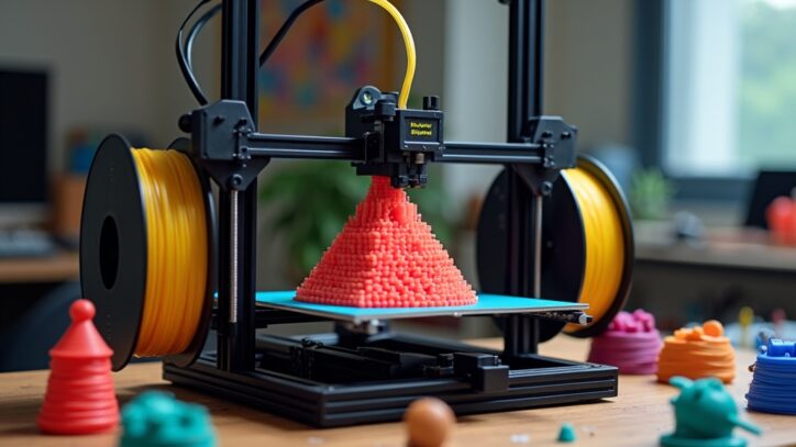
My Everyday Baseline for a 0.4 mm Nozzle
Duplicate the correct printer and filament presets before editing. Keep the original available so you can undo a change without losing a known starting point.
| Setting | Starting point | What changes it |
|---|---|---|
| Layer height | 0.20 mm | Nozzle diameter, detail, and print time |
| Walls / perimeters | 3 | Geometry, load direction, and line width |
| Top and bottom shells | 5 layers each | About 1 mm each at 0.20 mm layers; preserve thickness if layer height changes |
| Infill | 15–25%; gyroid or cubic | Roof support, stiffness, geometry, and test results |
| First layer | 0.20 mm; 15–25 mm/s for a cautious test | Plate, material, and a proven machine preset |
| Temperature and cooling | Correct filament preset | Spool guidance, flow demand, and part geometry |
| Retraction and acceleration | Correct machine preset | Extruder, hotend, motion system, and calibration |
Do not copy another printer’s start G-code, bed dimensions, temperature limits, or acceleration values. A profile for the right printer with the wrong nozzle selected is still the wrong profile.
Get the First Layer Right Before Adjusting the Rest
Clean the plate using its manufacturer’s instructions and check the selected plate type. Remove debris from the nozzle before probing, then run the bed-leveling or first-layer procedure your printer requires.
Look for connected lines without open gaps, heavy ridges, or nozzle scraping. If adjustment is necessary, use the manufacturer’s calibration procedure; changing the first-layer height field is not a substitute for correcting nozzle-to-bed distance.
- Lines remain separate: inspect first-layer calibration, extrusion, and plate cleanliness.
- Ridges build up or the nozzle drags: check whether the nozzle is too close or extrusion is excessive.
- The layer begins well but corners lift later: investigate drafts, material shrinkage, plate temperature, and contact area.
A brim can help a narrow or warp-prone part. It does not repair an unsuitable plate, a contaminated surface, or incorrect calibration. PETG can bond too strongly to smooth PEI; use the recommended surface or release layer. Prusa’s PETG guidance explains the plate compatibility issue.
Layer Height, Walls, and Infill Solve Different Problems
With a 0.4 mm nozzle, 0.20 mm layers are a useful compromise. Try 0.12–0.16 mm for smoother curves in the vertical direction, or 0.24–0.28 mm for faster rough prototypes when the nozzle profile supports them. Taller layers do not automatically produce stronger parts.
For another nozzle size, choose a matching preset. Prusa’s layer and perimeter documentation explains nozzle-related layer-height limits and minimum shell thickness. Five layers at 0.12 mm make a 0.60 mm shell, whereas five at 0.20 mm make a 1 mm shell.
I consider orientation and walls before making a large infill increase. Many parts benefit from a more substantial outer shell, but the best choice depends on where the load acts. Infill still helps support top surfaces and contributes to stiffness.
| Print purpose | Starting comparison | Check before use |
|---|---|---|
| Fit-only prototype | 2–3 walls; 10–15% infill | Critical dimensions and clearances |
| Organizer or general utility part | 3 walls; 15–25% infill | Top closure and everyday handling |
| Noncritical bracket or mount prototype | 4–6 walls; 25–40% infill as a test | Orientation, attachment points, deformation, and representative loading |
These are not load ratings. A part carrying sustained weight can creep, and a strong-looking print can separate between layers. Parts whose failure could injure someone need engineering review and appropriate validation.
Choose Temperature and Cooling for the Filament
Use the spool’s recommended range and a compatible filament preset first. The figures below are illustrative conventional-filament ranges, not replacements for those instructions. High-speed, filled, modified, and specialty blends may need different conditions.
| Material | Nozzle / bed examples | Cooling and environment |
|---|---|---|
| PLA | 200–220°C / 50–60°C | Often substantial part cooling after the first layers; avoid excessive enclosure heat |
| PETG | 230–250°C / 70–85°C | Often lower cooling than PLA; bridges may need more |
| ASA | 250–260°C / 90–110°C | Controlled enclosure conditions and generally limited part cooling |
Keep every setting within the printer, hotend, and build-plate ratings. Fan percentages do not transfer neatly between machines: 40% on one cooling system can behave differently on another.
For ASA, plan ventilation or source extraction as well as temperature control. An enclosure helps with drafts and warping but does not by itself control exposure to emissions. See Prusa’s ASA material guidance for printing conditions and precautions.
Speed Is Limited by How Much Plastic the Hotend Can Melt
For a conservative diagnostic print, outer walls around 35–55 mm/s and inner walls around 50–80 mm/s can be useful. A proven modern profile may run substantially faster; there is no reason to slow a working setup merely to match this article.
The important limit is extrusion demand. As a rough planning estimate, multiply line width × layer height × speed to get volumetric flow in mm³/s. At 0.45 mm wide, 0.20 mm high, and 100 mm/s, that is about 9 mm³/s. Actual slicer calculations account for bead geometry.
Exceeding the filament and hotend’s reliable flow capacity can cause under-extrusion even if the motion system handles the speed. Keep the profile’s flow limit until you have reason to calibrate it; Prusa’s maximum volumetric speed guide explains how this constrains print speed.
Retraction and Supports Need Their Own Checks
Start with your printer’s retraction preset. Direct-drive systems often need shorter retractions than Bowden systems, but a generic distance can be wrong for a particular hotend. Increasing retraction aggressively can introduce gaps or jams.
For stringing, inspect moisture, nozzle condition, and temperature before running a small retraction test. Dry filament according to its manufacturer’s guidance, using equipment and temperatures suitable for both filament and spool.
Before adding supports, compare orientations for both strength and surface quality. Check the sliced preview: overhang-angle conventions vary between slicers, so a copied “55 degrees” may not select the surfaces you expect.
Begin with the slicer’s support preset and test its contact gap and interface on a small sample. A zero contact gap suitable for some dissimilar support materials can fuse same-material supports to a part.
Printer + nozzle + filament + plate
0.20 mm · 3 walls · 15–25% infill
Typical 0.4 mm nozzle utility baseline
First layer + fit + layer bonding
One change + one test + written result
Use the P.R.I.N.T. Method™ Before a Long Print
Record these five decisions in your project notes. They connect the slicer profile to the job instead of leaving you with a list of numbers.
- P — Problem: What must this part solve?
- R — Requirements: What loads, temperatures, movement, and exposure matter?
- I — Interfaces: Which holes, clips, mating faces, and clearances must fit?
- N — Next-Best Materials & Methods: Which material, orientation, nozzle, and process fit the requirements?
- T — Test & Tune: What small sample can test the biggest uncertainty?
What I Check When the Baseline Fails
- Early lifting: plate compatibility, cleaning, first-layer calibration, and drafts.
- Gaps at higher speeds: filament feed, nozzle restriction, and volumetric flow demand.
- Weak layer bonding: orientation, extrusion consistency, temperature, and excessive cooling.
- Rough top surface: solid thickness, infill support beneath it, flow, and cooling.
- Poor fit: measurements, model clearance, first-layer swelling, and material shrinkage.
Change one variable, repeat the same small test, and compare the result. Once a profile works, save it with the printer, nozzle, material, and purpose in its name. Keep the model and slicer project so the result is repeatable.
Knowledge Check: Four Decisions That Matter
Choose your answer, then expand the explanation.
1. Can you transfer a complete profile to a different printer?
A. Yes, if both use PLA. B. Only after checking hardware compatibility.
Answer: B. Printer, nozzle, plate, extruder, and motion settings must match. Transfer the approach, then adapt the settings.
2. What happens to a five-layer shell when layers drop from 0.20 to 0.12 mm?
A. It becomes thinner. B. It stays 1 mm thick.
Answer: A. It drops from 1 mm to 0.60 mm. Adjust layer count or minimum shell thickness when appropriate.
3. Can a fast-moving printer still under-extrude?
A. Yes. B. Only with a damaged motor.
Answer: A. The hotend and filament may not support the requested extrusion flow.
4. How should you troubleshoot a new problem?
A. Change five settings. B. Change one variable and compare the same test.
Answer: B. A controlled comparison tells you which adjustment helped.
Frequently Asked Questions
Is 0.20 mm the best layer height for every nozzle?
No. It is a useful everyday starting point for a 0.4 mm nozzle. Smaller and larger nozzles need suitable profiles, and detail requirements may justify another height.
Will 100% infill make my print reliable?
No. It cannot correct weak layer bonding, unsuitable material, poor orientation, or a bad first layer. Choose infill alongside shell design and test the part for its intended use.
Should I slow down a printer that already prints well?
Not automatically. Keep a proven profile. Slower diagnostic settings help isolate problems when the existing result is poor or the material is unfamiliar.
Can I use the same profile for PLA and PETG?
Some geometry settings may carry over, but use a suitable filament preset for each. Temperature, cooling, flow limits, and plate compatibility need separate attention.
What should a beginner learn first?
Learn to select the correct profiles, inspect a first layer, preview supports, and judge a finished part. Follow the step-by-step beginner guide if the workflow is new.
Make Your Next Print Easier to Repeat
Start with a small part that tests the thing you care about: a mating hole, a clip, a flat base, or an overhang. Keep the settings that work and document the change that improves the result.
Which setting made the biggest difference on your printer? Share the machine, nozzle size, material, and symptom in the comments so other readers can understand the context.
