
Infill decision guide
Gyroid became the dependable default for makers who wanted a strong, three-dimensional internal structure without Grid’s same-layer intersections. Then larger printers, faster profiles, and longer production jobs changed the question. Makers began asking whether every cubic inch of a big part needed the same internal density.
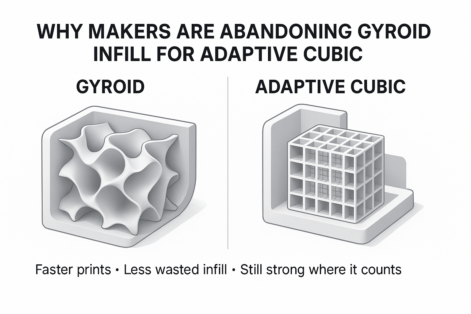
That is where Adaptive Cubic earns attention. It concentrates denser infill near the model’s outer surfaces while opening larger cavities toward the center. On the right geometry, that can reduce estimated time and filament without leaving top layers unsupported.
Quick answer: Choose Adaptive Cubic for large housings, organizers, display parts, prototypes, and other enclosed models when the slicer preview shows a meaningful time or material saving. Choose Gyroid when you want a more uniform internal network, expect mixed or twisting loads, print flexible material, or want to avoid infill paths that cross within the same layer.
The honest correction to the headline: makers are not abandoning Gyroid across the board. They are replacing it where Adaptive Cubic solves the actual problem more efficiently.
Efficiency-first pick
Adaptive Cubic is most persuasive inside a large enclosed volume where a uniform infill density would add time and material deep inside the part.
Consistency-first pick
Gyroid remains a smart choice when the load direction is uncertain, same-layer crossings are undesirable, or your existing profile already prints it cleanly.
Why are makers switching from Gyroid to Adaptive Cubic?
The switch is less about discovering a new “strongest infill” and more about ending a habit. Gyroid is easy to select, visually convincing, and useful in many parts. That does not mean its uniform repeating structure is the most efficient use of time and plastic in every model.
Adaptive Cubic changes the distribution rather than merely changing the shape. Prusa explains that its implementation becomes denser near the top, bottom, and sides while leaving larger cavities near the center. That is especially useful in large prints with substantial internal volume.
Three practical reasons drive the change:
- Large-part efficiency: less internal structure may be needed far from the shell.
- Top-layer support: the pattern becomes denser as it approaches model surfaces.
- Better decision visibility: modern slicer previews make it easy to compare time, grams, and internal spacing before committing to a long print.
Do not treat “Adaptive” as automatic engineering. The algorithm responds to part geometry and distance from surfaces; it does not know the real load path, screw torque, impact direction, heat exposure, or consequences of failure. A loaded boss or thin arm may still need more walls, a modifier, a different orientation, or a redesign.
Gyroid and Adaptive Cubic solve different problems
Gyroid: a continuous network without same-layer crossings
Gyroid uses a repeating three-dimensional curved structure. Prusa describes it as providing support in every direction, with a good strength-to-weight ratio and no paths that cross themselves within the same layer.
Those continuous curves can produce frequent changes in toolhead direction. On a fast or poorly tuned profile, the printer may sound busier or show resonance artifacts. That is profile-dependent—not proof that Gyroid is damaging the machine.
Adaptive Cubic: denser near surfaces, lighter in the center
Adaptive Cubic is based on corner-down cubic cells. The slicer refines cells near the model’s surfaces and allows larger cells farther inside. This can preserve useful support near walls and top layers while reducing internal fill where the geometry permits.
There is an important tradeoff the original draft missed: Adaptive Cubic can include paths that cross within the same layer. Straighter segments do not guarantee quieter motion, cleaner intersections, or less nozzle contact. Preview the toolpath and watch the first real print instead of assuming “cubic” automatically means calmer.
Slicer-name note: PrusaSlicer and Bambu Studio call this pattern Adaptive Cubic. Cura offers Cubic Subdivision, which pursues a similar variable-density goal. Treat them as comparable concepts, not guaranteed line-for-line implementations. Menus, algorithms, and estimates can change with slicer versions.
Gyroid vs Adaptive Cubic: practical comparison
| Decision point | Gyroid | Adaptive Cubic |
|---|---|---|
| Internal structure | Repeating curved three-dimensional network | Corner-down cubic cells that become larger toward the interior |
| Density distribution | Relatively consistent through the volume at the selected density | Denser near model surfaces and lighter toward the center |
| Best geometry | Small-to-large parts where a uniform internal network is useful | Large enclosed parts with enough interior space for cell sizes to vary |
| Print time and material | Can be competitive in small parts; may cost more in large infill-heavy volumes | Often saves time and material on large parts, but the preview must confirm it |
| Load behavior | Sensible starting point for mixed-direction or twisting loads | Can provide useful three-dimensional support, but variable density is not a stress analysis |
| Same-layer crossings | No Grid-style crossings within one layer | Paths can cross within a layer |
| Top-surface support | Depends on density, spacing, and top thickness | Designed to become denser near model surfaces, but top thickness still matters |
| Machine sound | Curves may sound busy at aggressive speed and acceleration | Straighter runs may sound calmer in places; crossings and short segments can still create noise |
| Best default? | Better when consistency and crossing-free paths matter | Better efficiency candidate for larger everyday prints |
For a speed-focused alternative that uses mostly linear toolpaths rather than variable cell density, compare Gyroid vs Cross Hatch for high-speed 3D printing.
Which infill should you choose?
Choose Adaptive Cubic when the empty middle is the opportunity
- The part is a large enclosure, organizer, housing, display model, jig body, or fit-check prototype.
- The outer shell carries most of the expected load.
- The slicer preview shows a meaningful reduction in time or grams.
- You need denser internal support near top surfaces without filling the entire center uniformly.
- You can validate the finished part before relying on it.
Keep Gyroid when uniform behavior matters more
- The part may be pushed, twisted, squeezed, or loaded from several directions.
- You are using TPU and want a smooth, connected internal network.
- You want to avoid infill paths that cross in the same layer.
- The part is small enough that Adaptive Cubic produces little or no estimated saving.
- Your proven Gyroid profile is already fast, clean, and repeatable.
Do not let either pattern hide a weak design
Most failures begin somewhere specific: a thin wall, a hole, a layer line, a snap fit, a screw boss, or a sharp inside corner. Global infill percentage is a blunt tool for a local problem.
If a bracket needs more capacity, first inspect orientation, wall count, material, layer bonding, fillets, and the load path. Then decide whether infill is the limiting factor. My deeper guide to infill density for strength, speed, and savings explains why simply jumping from 15% to 40% is rarely the smartest first move.
How to run a fair Gyroid vs Adaptive Cubic slicer test
A screenshot of two patterns is not a fair comparison. Use your actual model and profile.
- Duplicate the plate or project. Keep the same orientation, filament, layer height, walls, top and bottom thickness, speeds, acceleration, supports, and modifier settings.
- Change only the infill pattern. First compare both at the same displayed percentage to see what the slicer produces.
- Record time and material. Write down estimated duration, filament length, and grams. Nominal percentage does not guarantee equal material use between patterns.
- Inspect the preview. Look at the center spacing, top-surface support, wall connections, small islands, crossings, and the areas around bosses or holes.
- Match the comparison to the goal. If you are testing strength per gram, adjust density until material estimates are close. If you are testing production time, keep the required wall and top settings fixed.
- Print the critical region first. Crop the model or create a representative coupon that includes the real interface and load direction.
- Test the part in use. A clean print and a confident time estimate are not proof of durability.
Best habit: save both projects with the slicer version in the filename. If an update changes path planning later, you still know which profile produced the approved part.
Starter settings that keep infill in perspective
These are practical baselines for a 0.4 mm nozzle—not engineering guarantees. Use top and bottom thickness rather than copying a layer count blindly, because layer height changes what that count means.
| Print goal | Pattern and density to test | Shell starting point | What to inspect |
|---|---|---|---|
| Large visual model or enclosure | Adaptive Cubic, 8–15% | 2–3 walls; about 0.8–1.0 mm top thickness | Top bridging, broad flat areas, and center cell size |
| Everyday functional part | Adaptive Cubic or Gyroid, 15–20% | 3–4 walls; about 0.8–1.2 mm top and bottom thickness | Wall bonding, holes, bosses, and actual load direction |
| Non-safety-critical bracket or mount | Slice both, often 20–30% as a test range | 4–6 walls plus fillets or local reinforcement | Orientation, layer-line failure, fasteners, and creep |
| Flexible TPU part | Gyroid, often 10–20% | 2–4 walls according to desired flex | Compression feel, recovery, flow, and heat buildup |
If infill lines are incomplete, hairy, or poorly bonded, confirm flow, temperature, moisture, and volumetric limits before changing patterns. A controlled 3D-printer calibration sequence will tell you more than a random density increase.
Partner disclosure: The link in this note is a COEX partner link. If you buy through it, I may earn a commission at no extra cost to you. When inconsistent or wet filament clouds an infill test, start with a dry, known spool. Readers can shop COEX filament and use code 3DPRINTINGBYKEVIN for 15% off.
Use the P.R.I.N.T. Method before choosing infill
P — Problem: What must the part do: hold, cover, locate, cushion, display, or survive impact?
R — Requirements: Define load direction, temperature, service life, weight, appearance, print-time target, and cost of failure.
I — Interfaces: Mark every boss, hole, clip, bearing surface, screw, edge, and contact point. These areas often need local attention.
N — Next-Best Materials & Methods: Choose material, orientation, walls, geometry, and only then the infill pattern. Preview both Gyroid and Adaptive Cubic.
T — Test & Tune: Print the smallest representative section, apply the real load, document the result, and change one variable at a time.
For the complete workflow—from slicers and materials to calibration and troubleshooting—see P.R.I.N.T. It Practical: 3D Printing for Beginners.
Four-question infill knowledge check
1. Which pattern should you test first for a large, mostly hollow enclosure?
Answer: Adaptive Cubic. Its variable cell size is designed to reduce internal density away from model surfaces. Confirm the saving and top support in the preview.
2. Which pattern avoids paths crossing themselves within the same layer?
Answer: Gyroid. Adaptive Cubic is based on cubic paths that can cross within a layer.
3. Why is comparing both patterns at “15%” not a complete strength-per-weight test?
Answer: Different patterns can use different actual amounts of filament at the same displayed percentage. Compare estimated grams and, when strength per gram matters, adjust density until material use is similar.
4. What should you change first when a screw boss breaks away from a part?
Answer: Inspect the interface, orientation, wall count, fillets, layer adhesion, and local reinforcement. A global infill increase may add plastic everywhere except where the failure needs it most.
Questions makers ask about Gyroid and Adaptive Cubic
Is Adaptive Cubic stronger than Gyroid?
Not universally. Adaptive Cubic is designed around efficient density distribution, while Gyroid provides a more uniform three-dimensional network. The result depends on geometry, load direction, material, orientation, walls, layer bonding, and how the finished part is tested.
Is Adaptive Cubic always faster?
No. Its advantage is most likely in large parts with substantial internal volume. In a small model dominated by walls, holes, and short paths, the time difference may be negligible. Trust the preview for the exact model and profile.
Why can Gyroid sound loud on a high-speed printer?
The toolhead follows continuous curves and changes direction throughout the layer. Aggressive speed and acceleration can make that motion sound busy or expose resonance. Reduce infill speed or acceleration and check calibration before assuming the pattern is harmful.
Can Adaptive Cubic cause nozzle scraping?
Its lines can cross within the same layer, so poor flow control or excess material can make intersections more noticeable. Scraping can also come from over-extrusion, warping, loose mechanics, or travel settings. Diagnose the cause instead of blaming the pattern alone.
Is Cura’s Cubic Subdivision the same as Adaptive Cubic?
It is an analogous variable-density cubic option, but do not assume identical path generation across Cura, PrusaSlicer, and Bambu Studio. Compare the preview and estimates in the slicer version you actually use.
What is the best everyday infill percentage?
There is no universal number. For many ordinary parts, 15–20% is a useful test range when paired with adequate walls and top thickness. Decorative prints may need less; demanding parts require load-specific design and validation rather than a generic percentage.
The bottom line: Adaptive Cubic is a better default only when the part agrees
Adaptive Cubic is a smart efficiency tool, especially for large enclosed prints. It can put denser support near model surfaces and leave more open space in the center. That is a real advantage—but it is not evidence that Gyroid has become obsolete.
Gyroid still deserves the job when you want a uniform three-dimensional network, mixed-direction support, flexible behavior, or no same-layer crossings. The best choice is the one your preview can justify and your finished-part test can defend.
Which pattern won on your printer?
Slice the same model both ways, compare minutes and grams, then tell me your printer, slicer, material, density, and result in the comments. Those details make the comparison useful to the next maker.
Share your result Compare Gyroid and Cross HatchReference note: The pattern descriptions are grounded in the official Prusa infill-pattern guide, the Bambu Studio fill-pattern guide, and UltiMaker Cura’s infill settings documentation. Slicer behavior can change, so verify the preview in the version you use.
