
Updated August 28, 2026
More infill does not automatically make a 3D print better. It usually makes the part heavier, slower, and more expensive—and it may leave the real weak point unchanged.
The useful question is not, “What infill percentage is strongest?” It is, “What combination of orientation, material, walls, top and bottom thickness, infill, and geometry fits the load this part will actually see?”
Quick answer
Start most ordinary FDM prints at 10%–20% infill. For a functional part, begin around 15%–25% with at least three walls, then orient the part so the main load does not pull the layer lines apart. Increase walls before jumping to very high infill unless compression, stiffness, weight, or internal support is the actual problem.
My practical default: 15%–20% cubic, adaptive cubic, gyroid, or rectilinear infill; three walls; adequate top and bottom thickness; then a small test coupon or first article before production.
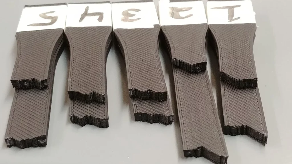
What 3D print infill density actually controls
Infill density is the amount of patterned material placed inside a printed part. Your slicer normally expresses it as a percentage:
- 0% infill: The inside is hollow, although walls and top or bottom layers may still be present.
- 10%–20% infill: A light internal network supports top surfaces and adds some stiffness without filling most of the interior.
- 30%–50% infill: More internal material improves support, stiffness, and resistance to crushing, but increases time and weight.
- 100% infill: The interior is intended to be solid. The slicer may handle this as solid fill rather than as an ordinary sparse pattern.
Density affects more than strength. It changes print time, filament use, part weight, top-surface support, stiffness, heat retention, and sometimes dimensional behavior. It can also affect whether a screw, insert, or drilled hole meets enough plastic inside the part.
It does not describe the whole print. A 20% part with four walls is not equivalent to a 20% part with two walls. Two slicers can also calculate nominal density differently for different patterns, so compare their material estimates and preview the actual toolpath.
Does infill density make a 3D print stronger?
Yes, increasing infill can improve strength, stiffness, and compression resistance. However, the size of that improvement depends on how the part is loaded.
A dense internal structure can help a block resist crushing. In a thin bracket under bending, adding an outer wall may place material farther from the neutral axis and do more useful work. If the bracket breaks between layers, changing its orientation or improving layer bonding can matter more than filling its center.
Before increasing infill, check these five strength levers
Keep the main tensile load from separating layer lines.
Add radii, ribs, gussets, or more section where stress concentrates.
Match stiffness, toughness, temperature, UV, and creep resistance to the job.
Use enough perimeters and a proven temperature, flow, and cooling profile.
Add density where internal support, stiffness, compression, or weight requires it.
That order is a planning guide, not a universal ranking. Published tests confirm that density can significantly change tensile or compressive results, but they also show that orientation, pattern, material, walls, and test method change the outcome. That is why a percentage from someone else’s test should be treated as a starting point—not a load rating for your part.
Best infill percentage by use case
Use this table to choose a sensible first slice. The final setting should come from the part’s geometry, material, print orientation, load, environment, and testing.
| Part or goal | Starting density | Good starting pattern | What to adjust first |
|---|---|---|---|
| Vase-mode or open decorative shell | 0% | None | Wall width and bottom thickness |
| Figurine or display model | 5%–10% | Lightning, support cubic, or rectilinear | Top-layer support and surface quality |
| General housing, organizer, or toy | 10%–20% | Rectilinear, cubic, or adaptive cubic | Walls, top/bottom thickness, and fit |
| Functional bracket or tool | 15%–25% | Cubic or gyroid | Orientation, three to five walls, radii, and material |
| Stiff or compression-loaded part | 25%–40% | Cubic, triangles, or tested honeycomb | Compression direction, buckling, and local reinforcement |
| Safety-critical or highly loaded part | No percentage is automatically safe | Select after testing | Engineering analysis, process control, test samples, and an appropriate safety factor |
Important: Do not use this table as certification for lifting, climbing, vehicle, medical, electrical-safety, pressure, or other failure-sensitive parts. A printed plastic component can fail from fatigue, creep, heat, UV exposure, chemical contact, or a hidden layer-bond defect even when the first test looks good.
Which infill pattern should you choose?
Pattern names and implementations differ across Cura, PrusaSlicer, OrcaSlicer, Bambu Studio, and Creality Print. Use the slicer preview to confirm what your selected pattern is actually doing.
| Pattern | Best use | Advantages | Watch for |
|---|---|---|---|
| Rectilinear or lines | Fast prototypes and general printing | Simple toolpaths, efficient material use, useful top support | Direction-dependent behavior |
| Grid | Fast, rigid general parts | Good support and familiar behavior | Same-layer crossings can accumulate material and cause nozzle contact on some fast prints |
| Cubic | Functional parts with loads from more than one direction | Three-dimensional internal structure and a strong general-purpose balance | More motion and time than simple lines |
| Gyroid | Multi-directional loading, vibration, or non-crossing toolpaths | Continuous curved paths and relatively balanced behavior | Longer curved toolpaths; it is not automatically strongest for every load |
| Adaptive cubic | Large models with substantial internal volume | Denser near walls and sparse in open interior areas, reducing waste | Not a uniform structure; verify the regions that carry load |
| Lightning or support cubic | Display models that mainly need top-surface support | Very low material use and shorter print time | Not intended to maximize mechanical strength |
| Triangles or honeycomb | Rigidity or compression after application-specific testing | Can perform well under certain loads | More direction changes, crossings, material, or print time |
| Concentric | Flexible parts and shapes that should follow outer contours | Predictable contour-following flex | Poor choice for loads that need cross-part reinforcement |
Be cautious with the word isotropic. Cubic and gyroid patterns can distribute internal material in three dimensions, but an FDM part is still affected by layer direction and interlayer bonding. No sparse pattern makes the entire printed part equally strong in every direction.
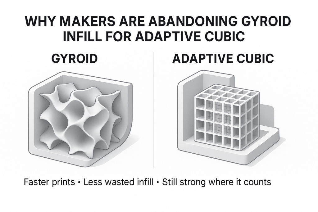
For more detail, compare Gyroid and Cross Hatch for high-speed printing, then see why Adaptive Cubic can make sense for large-volume parts.
The P.R.I.N.T. infill decision planner
I use the P.R.I.N.T. Method™ to turn a slicer guess into a repeatable decision.
Build your starting profile
- Problem: What must the part do—look good, support top layers, resist bending, survive impact, carry compression, or simply feel heavier?
- Requirements: Identify the load direction, expected force, temperature, UV, moisture, chemicals, allowable deflection, target life, and consequence of failure.
- Interfaces: Mark screw bosses, inserts, bearing seats, holes, thin necks, fillets, and contact surfaces. These areas may need more walls or local modifiers rather than dense infill everywhere.
- Next-Best Materials & Methods: Pick the material, orientation, wall count, pattern, and starting density as one system. Preview the toolpath before printing.
- Test & Tune: Print a small coupon or one first article. Change one variable at a time, record time and grams, then test in the real load direction.
If you want the complete planning workflow, P.R.I.N.T. It: Practical 3D Printing for Beginners connects slicer settings with materials, calibration, troubleshooting, and useful-part design.
A stronger part without wasting filament
When a print needs more strength, do not jump from 15% to 80% infill and hope. Work through these changes in order:
- Reorient the model. Try to keep major tensile and bending stresses within layers rather than pulling layers apart.
- Improve the geometry. Add fillets at inside corners, gussets near brackets, thicker sections around holes, or a larger load-bearing area.
- Add walls. Moving from two to three or four walls often adds useful strength where bending stress is highest.
- Check layer bonding. Confirm filament dryness, temperature, flow, speed, enclosure needs, and cooling for the chosen material.
- Increase top and bottom thickness when surfaces are the problem. Sparse top layers may need more solid thickness, closer internal support, slower top-surface speed, or a combination.
- Add density selectively. Use modifier meshes or local reinforcement around screws, inserts, contact points, and compression zones when your slicer supports them.
- Test the revised part. A promising slicer preview is not a strength test.
For general failure diagnosis, use this 3D printing troubleshooting guide. If a fastener is the weak point, read why screws strip 3D-printed parts before adding infill to the entire model.
When higher infill is the right choice
Higher density is not wrong. It is useful when the interior is doing a specific job:
- The part carries a substantial compressive load or must resist crushing.
- You need greater stiffness and cannot change the external geometry.
- A thin top surface needs shorter bridging spans, and more top thickness alone is not enough.
- You plan to drill, tap, machine, or install hardware into an internal region.
- The part needs a specific weight, center of gravity, damping response, or tactile feel.
- Your test data shows that density is the limiting variable.
Even then, 100% can introduce long print times, extra heat, shrinkage stress, or overextrusion problems. Slice 40%, 60%, and 100% versions and compare estimated grams, time, toolpaths, and risk before committing to the solid part.
Infill troubleshooting: fix the symptom, not the percentage
| Symptom | Likely cause | Try this first |
|---|---|---|
| Top surface sags or shows gaps | Unsupported span, too little solid top thickness, poor cooling, or excessive speed | Add top thickness, slow the top layers, check cooling, then modestly increase infill if needed |
| Nozzle clicks or strikes infill | Crossing paths, overextrusion, warping, or loose mechanics | Verify flow and mechanics; try a non-crossing pattern such as gyroid |
| Bracket snaps at a layer line | Weak orientation or layer bonding | Reorient, improve bonding, and redesign the stress concentration before adding infill |
| Wall buckles inward | Insufficient wall support or wide internal spacing | Add a wall or increase density locally |
| Print is strong but too slow | Uniform density where it is not needed | Try adaptive cubic, local modifiers, thicker layers, or a larger nozzle after validating quality |
Run a three-slice comparison before printing
You can learn a great deal without extruding a gram of filament. Duplicate the same model and compare these three profiles:
- Profile A: 15% infill with three walls.
- Profile B: 15% infill with four walls.
- Profile C: 30% infill with three walls.
Record the estimated print time, material weight, wall time, infill time, and top-surface preview. If B adds less cost than C and places material where the part is stressed, print B first. If the part is compression-loaded through its center, C may be the more informative test.
For a production decision, print at least three identical samples of the leading setup and load them in the real direction. A single successful part does not reveal process variation.
Material still matters
Infill cannot rescue a material that does not fit the environment. PLA can be stiff and easy to print but may creep or soften in heat. PETG can offer useful toughness and chemical resistance but behaves differently under sustained load. ABS or ASA may suit warmer environments, while nylon can add toughness but requires careful moisture control and process setup.
Partner disclosure: I partner with COEX. If you need U.S.-made PLA, PETG, ABS, ASA, or specialty filament, you can shop COEX filament and use code 3DPRINTINGBYKEVIN for 15% off when eligible. I may earn a commission at no additional cost to you.
Quick knowledge check
Choose your answer, then open the answer panel. Each answer stays collapsed until you select it.
1. A bracket breaks between layers. What should you examine first?
A. Change its color B. Orientation and layer bonding C. Use 100% infill
Reveal answer
B. More infill may leave the weak interlayer plane unchanged.
2. Which setting is a practical starting range for many ordinary prints?
A. 10%–20% B. 70%–90% C. Always 100%
Reveal answer
A. It often provides enough internal support without excessive time or material.
3. Which pattern is designed mainly to support top surfaces while saving material?
A. Lightning or support cubic B. Concentric C. Solid fill
Reveal answer
A. These patterns prioritize internal support efficiency rather than maximum mechanical strength.
4. What is the best way to confirm a functional infill setting?
A. Copy a social-media profile B. Trust the slicer estimate C. Test repeat samples in the real load direction
Reveal answer
C. Real testing captures geometry, material, orientation, bonding, and process variation together.
Frequently asked questions
Is 20% infill strong enough?
It is a useful starting point for many ordinary and lightly loaded parts, especially with suitable orientation, material, geometry, and at least three walls. It is not a universal load rating. Test the actual part if failure matters.
What is the strongest infill pattern?
There is no single winner for every material and load. Cubic and gyroid are good multi-directional starting points; triangles or honeycomb may perform well in certain stiffness or compression tests. Orientation, walls, material, and geometry can outweigh the pattern choice.
What is the fastest infill pattern?
Rectilinear or line infill is usually among the fastest mechanical sparse patterns because the toolpath is simple. For a display model that only needs internal support beneath top surfaces, lightning or support cubic may use even less time and material.
Should I add walls or more infill?
Add walls first when the part fails at its outer section or under bending. Add infill when the interior must support compression, prevent wall buckling, support top surfaces, or provide local material around an interface. A three-slice comparison will show the time and material tradeoff.
Is 100% infill ever necessary?
Sometimes. A part may need machining allowance, internal thread engagement, weight, heat conduction, crushing resistance, or a test-controlled solid section. But 100% is rarely the most efficient automatic fix for a weak print.
Why can grid infill make a scraping noise?
Grid prints intersecting lines within the same layer. Small amounts of material can build at those crossings, particularly if flow, cooling, or speed is not well tuned. The nozzle may contact the raised intersections. Check calibration and mechanics, then consider a non-crossing pattern.
The practical takeaway
The best infill density is the lowest tested setting that supports the surfaces and meets the part’s real performance requirements. For many prints, that begins around 10%–20%. Functional parts often benefit more from better orientation, geometry, walls, and layer bonding than from a nearly solid interior.
Start with a defensible profile, preview it, print a test, and change one variable at a time. That approach saves more filament—and prevents more failures—than treating infill percentage as a strength dial.
What infill setting has worked best for your parts? Share the material, pattern, density, wall count, and load in the comments. Those details make your result useful to the next maker.
Technical references
- Prusa Knowledge Base: Infill
- Prusa Knowledge Base: Infill patterns
- UltiMaker Cura: Infill settings
- Bambu Lab Wiki: Fill pattern introduction
- Peer-reviewed study: Effects of infill density, wall perimeter, and layer height
- Peer-reviewed study: Infill density and mechanical properties of ABS and CF-ABS
