
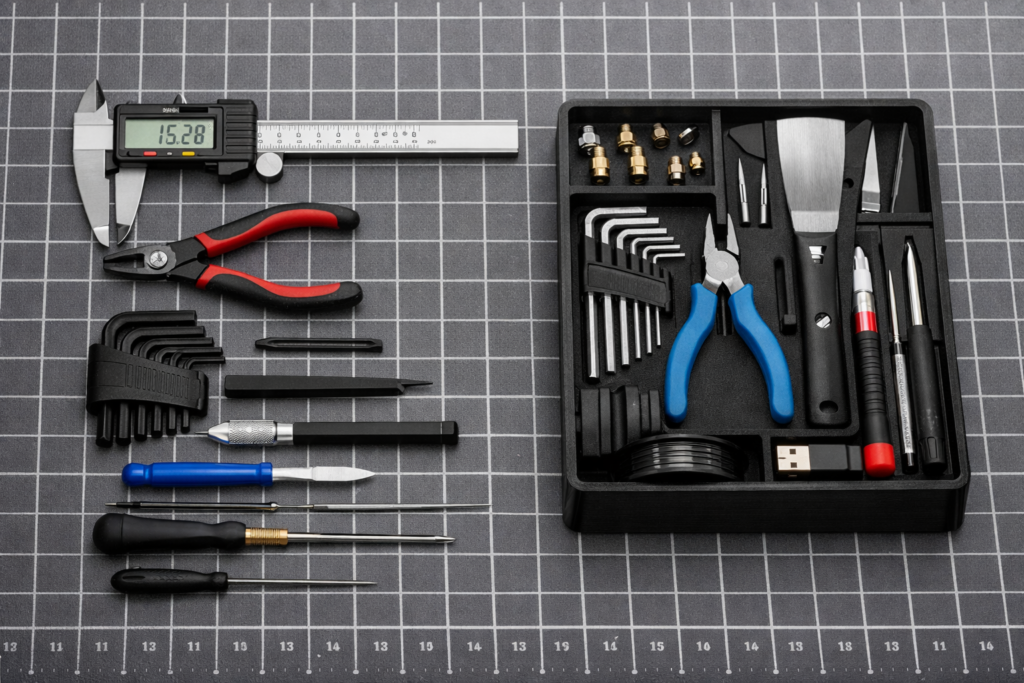
A fitted tool tray is one of those 3D prints that can earn its place every day. The problem is that tracing odd shapes, setting clearances, and arranging every pocket can turn a simple organizer into a long CAD session.
GridPilot takes a different route: photograph the tools, let the software detect their outlines, arrange the pockets, preview the tray, and export a file for production. That is a compelling promise for makers who care more about solving a messy-drawer problem than becoming expert CAD users.
Quick answer
GridPilot appears most useful for custom Gridfinity-style trays, workshop organizers, and fitted holders where speed matters more than engineering-level control. Its current workflow can define a Gridfinity or custom-size workspace, detect tools from photos, arrange pockets, add labels, preview the layout, and export 3MF or DXF files.
It does not eliminate the maker’s job. You still need to confirm drawer dimensions, pocket access, printability, material choice, and real-world fit. For a safety-critical, load-bearing, or tightly toleranced part, use measured CAD and appropriate engineering review instead.
What Does GridPilot Do?
GridPilot is an online tray-design tool built around a focused task: turning real tools or objects into fitted pockets without manually drawing every outline. According to its current workflow, users can start with standard Gridfinity units or enter custom workspace dimensions.
You can then add tools through photo detection or manual entry, arrange them with drag-and-drop controls, preview the result, and download a 3MF for 3D printing or a DXF for another fabrication workflow. GridPilot currently says designing and previewing are free, while exports are governed by its current plans.
Define the workspace
Enter the Gridfinity footprint or the custom dimensions available in the drawer, case, or work area.
Add the tools
Upload clear photographs for AI outline detection or add items manually when that makes more sense.
Arrange the layout
Move the detected shapes, use the arrangement tools, create zones, and add labels where useful.
Preview and export
Inspect the tray in 3D, then export 3MF for a slicer or DXF for a compatible cutting workflow.
What Is Gridfinity—and Why Does It Matter?
Gridfinity is an open, community-expanded modular organization system introduced by Zack Freedman. Its repeatable grid lets bins, tool holders, and trays share a common footprint, so makers can rearrange a drawer without rebuilding the entire storage system.
That modularity is what makes a photo-based generator interesting. A fitted pocket can hold a particular caliper, cutter, driver, or gauge, while the Gridfinity footprint lets the finished holder live beside compatible bins and other modules.
GridPilot vs. Manual CAD vs. Generic Bins
The right workflow depends on the job. GridPilot may shorten the outline-and-layout stage, but that advantage matters only when a fitted tray is the right solution in the first place.
| Decision | GridPilot photo workflow | Manual CAD | Generic Gridfinity bins |
|---|---|---|---|
| Best use | Fast fitted trays and organizer layouts | Exact interfaces, mechanical features, and controlled geometry | Loose parts, consumables, and changing inventories |
| Starting point | Workspace dimensions plus tool photos or manual objects | Measurements, sketches, constraints, and modeled features | Choose an existing bin size |
| Learning curve | Lower for the intended organizer workflow | Higher; CAD skill and dimensional judgment are required | Lowest when a ready-made model fits |
| Design control | Focused layout and pocket controls | Highest control over every feature | Little or no customization |
| Maker checks still required | Outline accuracy, access, depth, spacing, slicing, and fit | Measurements, clearances, strength, slicing, and fit | Drawer fit, bin size, labeling, and print quality |
| Weak fit | Safety-critical or tightly controlled mechanical parts | A simple storage job that does not justify the design time | Tools that need protection or a clearly assigned location |
A Practical Photo-to-3MF Workflow
1. Start With the Drawer, Not the Photo
Measure the usable width, depth, and height. Check for screw heads, drawer slides, curved corners, liners, lips, and anything else that reduces the real space. Include the height of the tools, not only the tray.
2. Choose Only the Tools That Belong Together
Build the tray around a workflow: printer maintenance, electronics assembly, nozzle changes, model finishing, or measurement. A crowded tray can look efficient on screen while becoming frustrating to use.
3. Take a Clean Overhead Photo
Lay the tools flat, separate their outlines, use even light, and keep the camera as square to the surface as possible. Shadows, overlap, glare, and a steep camera angle can make any outline-detection workflow harder to trust.
4. Inspect Every Detected Shape
AI detection is a starting point, not an inspection report. Look for missed handles, merged shadows, narrow features, protrusions, and places where the real tool is thicker than its top-view silhouette suggests.
5. Design for Fingers, Not Just Fit
Leave a practical grip area around each tool. A pocket that traces an object beautifully can still fail if the user cannot lift the tool. Deep pockets may need finger scoops or exposed handle areas.
6. Preview, Export, and Inspect Again in the Slicer
A 3MF export still needs a slicer and a suitable printer profile. Preview every layer. Look for thin walls, tiny isolated sections, unsupported features, questionable first-layer geometry, and a tray footprint that exceeds the selected build plate.
7. Print the Smallest Useful Test
If the project is large, do not use a full drawer of filament to discover that one pocket is too tight. Test the most uncertain tool or a representative section first. Fit depends on the model, material, extrusion behavior, first-layer condition, and calibration of your specific machine.
Before You Start the Full Print
- Confirm the drawer’s usable width, depth, and closed height.
- Confirm the tray fits the printer’s build area—or plan clean module divisions.
- Check every detected outline against the real object.
- Leave room to grip and remove each tool.
- Choose pocket depth based on stability and access.
- Inspect the complete layer preview in the slicer.
- Run a fit sample before a long or material-heavy job.
Plan the Tray With the P.R.I.N.T. Method™
GridPilot can accelerate geometry, but a useful organizer still begins with a defined problem. This is how I would apply my P.R.I.N.T. Method before committing to the full tray.
P — Problem
What is actually wrong: wasted search time, damaged tools, a cluttered drawer, or missing-tool control?
R — Requirements
List the environment, drawer size, tool set, access needs, labels, modularity, and expected daily use.
I — Interfaces
Measure the drawer, Gridfinity footprint, tool envelopes, handle access, clearances, and anything the tray touches.
N — Next-Best Materials & Methods
Decide whether GridPilot, manual CAD, or generic bins are best, then choose the simplest material and print plan that meets the requirements.
T — Test & Tune
Print a small uncertain section, check real fit, change one variable at a time, and document the final setup.
Your go/no-go question
Will the finished tray improve the workflow enough to justify its print time, material, and dedicated space?
PLA or PETG for a Custom Tool Tray?
PLA is the sensible starting point for most indoor drawers. It is easy to print, stays dimensionally stable under ordinary indoor conditions, and works well for prototypes and light-duty organizers.
PETG may be preferable when the tray needs more toughness or will live in a harder-working shop environment. It can be more forgiving of bumps and flexing, but stringing and dimensional behavior may require extra tuning.
Neither material choice should be made from the material name alone. Consider heat, chemicals, UV exposure, loads, cleaning products, and the consequences of failure. A parked vehicle, hot shop surface, or industrial environment may demand a different material and more controlled validation.
Where GridPilot Looks Most Useful
- 3D printer maintenance kits: flush cutters, scrapers, deburring tools, nozzle wrenches, hex keys, and spare nozzles.
- Electronics benches: tweezers, small pliers, cutters, probes, adapters, and soldering accessories.
- Measurement drawers: calipers, gauges, rules, squares, and specialty inspection tools that need protection.
- Craft and model-making stations: knives, sculpting tools, brushes, punches, and finishing supplies.
- Small-shop tool control: assigned locations that make a missing tool visible before the next job begins.
Where I Would Still Choose Manual CAD
A top-view photo cannot communicate every design requirement. Manual, dimension-driven CAD remains the better path when a part needs controlled snap fits, fasteners, load paths, moving interfaces, complex depths, or a documented dimensional basis.
It is also the safer choice when failure could damage expensive equipment or injure someone. An organizer generator is not a substitute for engineering analysis, manufacturer requirements, or testing appropriate to the risk.
If you are uncertain about your printer’s real clearance capability, the Maker’s Muse tolerance test is a useful reminder that modeled gaps and printed gaps are not automatically the same. Calibrate and test on your machine rather than copying a clearance value blindly.
My First-Look Verdict
GridPilot is aimed at the right bottleneck: the repetitive work between seeing an organization problem and having a printable fitted layout.
Its strongest potential is not “AI designs everything.” It is “AI gives the maker a faster first layout for a narrow, useful class of projects.” That is a far more believable and practical role.
For now, I would treat it as a promising organizer workflow, not a proven replacement for CAD or a finished-print guarantee. A true hands-on review should include the source photo, detected outlines, exported file, slicer settings, print time, material, first fit, revisions, and long-term use. I will update this first look when that evidence is available.
Knowledge Check: Would This Workflow Fit Your Project?
Choose your answer, then open each question to check it.
1. What should you measure first: the tool photo or the usable drawer space?
2. Does a clean AI-detected outline guarantee that the printed pocket will fit?
3. When is a generic bin often better than a fitted tray?
4. What is the safest first print for a large organizer?
Frequently Asked Questions
Is GridPilot a replacement for CAD?
No. It is a focused shortcut for fitted trays and organizer layouts. Measured CAD remains more appropriate when you need controlled mechanical geometry, exact interfaces, or features outside the generator’s intended workflow.
Do I need a Gridfinity drawer to use it?
Not necessarily. GridPilot’s current site says you can define standard Gridfinity units or use custom tray dimensions. Check the current setup options before starting your design.
What files can GridPilot export?
GridPilot currently advertises 3MF for 3D printing and DXF for compatible cutting workflows. Confirm the current export features and plan terms on its official site before purchasing.
Do I still need slicer software?
Yes. The exported 3MF must still be opened, configured, and inspected in a slicer that supports your printer. Confirm the printer, nozzle, material, layer height, walls, infill, first layer, and complete toolpath preview.
Should I print a complete drawer on the first try?
Usually not. A smaller fit test can reveal clearance, pocket-depth, elephant’s-foot, and access problems while using far less time and filament.
Is GridPilot free?
GridPilot currently states that users can design and preview trays for free and pay according to its export plans. Pricing and plan details can change, so use the official site for the latest terms.
Has this article documented a finished GridPilot print?
Not yet. This is a first look at the current workflow and its practical fit for functional 3D printing. The article should be updated with original photos, export screenshots, slicer settings, print results, fit corrections, and use notes after a complete hands-on test.
Would You Use a Photo to Design Your Next Tool Tray?
The most useful test is not whether the AI output looks impressive on screen. It is whether the finished tray saves time, protects the tools, fits the drawer, and remains easy to use after the novelty wears off.
Tell me in the comments what you would organize first—and which fit detail would worry you most. If you have already printed a photo-generated tray, share what worked, what needed revision, and what you would change before the next export.
Editorial note: Software features, export terms, and pricing can change. Verify the current details on GridPilot’s official site. This article does not recommend organizer-generated files for safety-critical, load-bearing, regulated, or high-consequence applications.
