
Functional 3D Printing • Fastener Design • Practical Testing
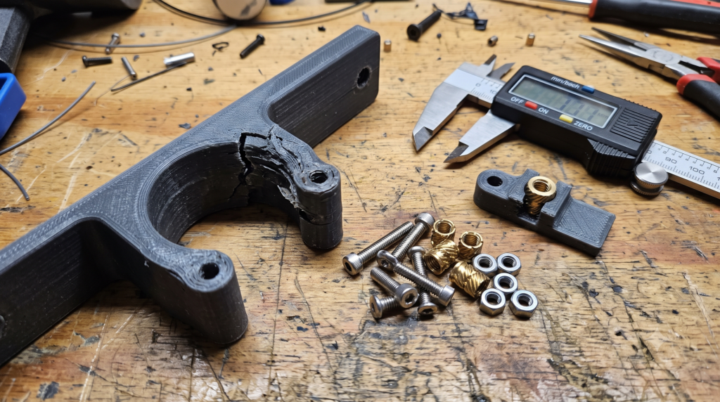
The screw turned normally. The parts pulled together. Then a thin white line appeared beside the hole—or the boss split before the assembly was even finished.
That failure is easy to blame on weak filament. Often, however, the crack began with the interface: a hole that was too tight, a screw head that acted like a wedge, a thin wall around the boss, a layer direction that invited splitting, or more tightening force than the plastic joint needed.
A functional print does not become dependable merely because the model finished and the screw fits. The fastener, printed geometry, material, orientation, installation method, and real load must work as one system.
Quick Answer: Why Did the 3D Print Crack Around the Screw?
A screw can crack a 3D-printed part when it forces an undersized hole outward, wedges into a countersink, bottoms out, is overtightened, or concentrates load in a boss that is too thin or poorly oriented. Layer bonding and material behavior can make the result worse, but adding infill alone may not repair the fastener interface.
The practical fix: identify what the joint must do, select the right fastening method, provide enough material around it, keep the load from peeling layers apart, and print a small fastener coupon before committing to the complete part.
The Six Fastener Problems Hiding Behind the Crack
1The Hole Is Acting Like an Interference Fit
A round hole in CAD may print slightly undersized or uneven because of extrusion width, machine calibration, material shrinkage, layer height, orientation, and slicer compensation. Driving a screw into that hole can push the surrounding plastic outward.
If the design was intended to provide clearance, the screw should not need to cut or displace the wall. If the screw is intentionally forming threads, its pilot hole must match that exact fastener, material, and printed test—not a universal guess.
2The Boss Has Too Little Material
A hole close to an edge, surrounded by only a few extrusion paths, or perched on a narrow boss has little room to distribute stress. The CAD model may look substantial while the sliced toolpath reveals a thin, interrupted shell.
Inspect the slicer preview. Strengthen the local geometry with a larger boss, more purposeful wall thickness, fillets, ribs, or a washer-bearing surface when the space and load allow it.
3The Screw Head Is Wedge-Loading the Part
A countersunk head converts tightening into outward pressure against the countersink. In a small or brittle printed boss, that wedge can start a radial crack. A flat-bearing screw head or washer may spread clamping force more gently, but it still cannot rescue weak geometry.
Choose the head style because it suits the joint—not only because it sits flush.
4The Layers Open in the Load Direction
FDM parts are direction-dependent. If tightening or service load tries to separate layer planes, a screw boss may split even when the same geometry survives in another orientation. More infill does not automatically strengthen the layer-to-layer path around the hole.
Rotate the part, change how the boss joins the body, or redesign the load path so the fastener clamps the part instead of peeling it apart.
5The Joint Is Overtightened—or the Screw Bottomed Out
Plastic does not need the same tightening habit used on a steel bracket. Continuing to turn after the joint is seated can crush the bearing surface, strip formed threads, spin an insert, or split the boss.
A screw that bottoms in a blind hole can also push against the part instead of clamping the mating pieces. Confirm screw length, hole depth, thread engagement, and the actual seating surfaces before assembly.
6The Fastener Method Does Not Match Repeated Service
A screw driven directly into plastic may be reasonable for a cover installed once. It is a poor choice when the joint will be opened every week. Repeated assembly can wear printed or formed plastic threads long before the rest of the part reaches the end of its useful life.
For serviceable assemblies, consider a captive nut, through-bolt, or properly designed threaded insert.
Measure before blaming the printer: Kevin’s 3D-printed tolerance-gauge guide explains why a small physical test can reveal more than another full-size reprint.
Direct Screw, Printed Thread, Captive Nut, or Heat-Set Insert?
There is no single “strongest” answer for every part. The useful choice depends on assembly cycles, available space, access to both sides, load direction, material, installation control, and what happens if the joint loosens.
| Fastener strategy | Good starting use | Main advantage | What can go wrong |
|---|---|---|---|
| Screw directly into a printed pilot | Light-duty cover or one-time assembly | Simple, compact, and low-cost | Wrong pilot size can split the boss; repeated use can wear the plastic |
| Printed thread | Larger, coarse threads; knobs, caps, prototypes, or low-cycle parts | No extra hardware | Small threads may print poorly; fit and wear depend heavily on orientation and calibration |
| Captured or captive nut | Serviceable joints where a nut pocket and assembly access are practical | Reusable metal thread without heat installation | A loose pocket can spin; a tight pocket can crack; access and insertion sequence matter |
| Heat-set threaded insert | Compact, repeatedly assembled thermoplastic parts | Durable metal thread with controlled placement | Wrong hole size, weak boss, poor alignment, overheating, or bottoming screw can reduce performance |
| Through-bolt, nut, and washer | Joints with access to both sides and room to spread clamp load | Clear hardware load path and easy inspection | Still crushes plastic if overtightened; may need a spacer or compression limiter |
My practical rule: if the joint will be opened repeatedly, do not make a small printed thread carry a job that inexpensive metal hardware can handle more predictably. If access to the back is easy, a through-bolt or captured nut may be simpler than installing an insert. If compact serviceable threads matter, a correctly designed insert becomes more attractive.
Read the Failure Before You Redesign the Part
The crack pattern is not a perfect laboratory diagnosis, but it can point you toward the first variable worth testing.
- Radial crack appeared while tightening: inspect pilot-hole fit, countersink wedging, boss thickness, and tightening force.
- Split followed a visible layer line: inspect orientation, layer bonding, local walls, and whether the load peels the layers apart.
- Hole turned white but did not split: whitening can indicate local plastic strain; stop, unload the joint, and inspect before continuing.
- Screw spins without clamping: the plastic thread may be stripped, the pilot may be too large, or the screw may be the wrong style.
- Insert spins or pulls out: check the insert type, printed hole, boss geometry, installation alignment, and surrounding material.
- Crack appeared after days or weeks: examine sustained clamp load, heat, vibration, creep, chemical exposure, and changing service conditions.
Stop when failure has consequences. A redesigned FDM fastener joint is not automatically suitable for personal safety, pressure, fuel, flame, high voltage, structural vehicle systems, regulated medical use, lifting, or another high-consequence application. Use an approved part or qualified engineering review where failure could cause harm.
What Insert Manufacturers Say Matters
Threaded inserts are useful, but the brass hardware does not erase the surrounding plastic design. The SPIROL Inserts for Plastics Design Guide emphasizes that correct hole size is critical, the hole should be deeper than the insert, the assembly screw should not bottom out, and boss diameter or wall thickness affects performance.
UltiMaker’s heat-set insert guide explains how a heated insert softens thermoplastic around its knurled exterior and notes that the result still depends on the insert, material, print settings, and hole accuracy.
That is why this article does not give one universal hole diameter or soldering-iron temperature. Start with the dimensional guidance for the exact insert, account for your printer and material, and validate the complete printed joint with a test coupon.
Apply Kevin’s P.R.I.N.T. Method™ to the Fastener Joint
This is the same problem-first thinking used for broken brackets and clips. A successful replacement must fit the surviving equipment, accept its hardware, resist the real load, and remain suitable for its environment.
The Five-Minute P.R.I.N.T. Fastener Fit Planner
Copy these answers into your project notes or print this section before opening CAD. The blanks are deliberate: your hardware and insert documentation—not a generic online number—should supply the final dimensions.
Print a Fastener Coupon, Not the Whole Part
Isolate the screw boss and enough surrounding geometry to preserve its real wall structure and layer direction. A useful coupon can compare two or three hole sizes, but change only the variable you intend to study.
- Use the same printer, nozzle, filament, layer height, wall settings, and orientation planned for the final part.
- Label each hole or pocket directly in the model so the result cannot be mixed up later.
- Use the actual production screw, nut, washer, or insert—not a hardware substitute that merely looks similar.
- Inspect the sliced walls around the hole before printing.
- Install the hardware consistently and stop if the plastic whitens, bulges, cracks, or the insert drifts out of square.
- Test the joint in its real load direction, then record which version passed and why.
For work where dimensions and repeatability matter, see how 3D Printing by Kevin approaches precision parts, tolerances, and threaded inserts.
Do Walls, Infill, and Material Still Matter?
Yes—but they solve different parts of the problem.
- Local walls and boss geometry determine how much printed material surrounds the hole and how smoothly the load enters the part.
- Infill can support the interior, but a high percentage does not automatically repair a thin outer boss, a wedge-loaded countersink, or weak layer orientation.
- Material affects stiffness, ductility, heat behavior, creep, layer bonding, and installation response. The material name alone does not guarantee a safe joint.
- Orientation changes the relationship between layers, hole shape, support needs, fastener load, and surface accuracy.
- Tightening control determines whether the joint is seated—or quietly being crushed.
Keep the exact filament brand, color, lot if available, drying history, profile, orientation, hardware, and revision with the test result. That record is far more useful than remembering that the successful part was simply “PETG.”
Affiliate disclosure: This article may contain affiliate links. If you make a qualifying purchase through one of these links, 3D Printing by Kevin may earn a commission without adding a separate charge to your purchase. Recommendations are selected for their relevance and potential usefulness to the reader.
If your project requirements point to a material available from Kevin’s filament partner, you can compare COEX filament and use code 3DPRINTINGBYKEVIN for 15% off eligible purchases. A consistent filament cannot fix a poorly designed screw boss, but a documented material makes a successful test easier to repeat.
For additional independent design challenges and 3D-printing education, explore Maker’s Muse.
Build the Whole Part Around Better Decisions
P.R.I.N.T. It: Practical 3D Printing for Beginners is Kevin’s 40-page, 2026 Expanded Edition covering setup, slicers, materials, calibration, replacement parts, maintenance, troubleshooting, and the complete P.R.I.N.T. Method™.
Use it beside your printer when you want a structured path from a digital model to a part that fits, functions, and teaches you what to improve next.
Four-Question Practical Knowledge Check
Choose your answer before opening each explanation.
1. A clearance screw needs force to enter the printed hole. Should you tighten it until it seats?
2. Will 100% infill automatically stop a countersunk screw from cracking a thin boss?
3. Which is automatically better: a heat-set insert or a captive nut?
4. Why should a fastener coupon use the final part’s orientation and settings?
Frequently Asked Questions
Can I drive a screw directly into a 3D-printed part?
What pilot-hole size should I use for a screw or heat-set insert?
Are heat-set inserts stronger than printed threads?
Can I put heat-set inserts into PLA, PETG, ABS, or ASA?
Will a washer stop the part from cracking?
Should I repair the crack with glue?
What Failed on Your Part?
Was it a split screw boss, a spinning insert, a stripped plastic thread, or a countersink that cracked during assembly? Share the printer, material, fastener, orientation, and when the failure appeared in the comments. Those clues make the discussion useful to the next maker facing the same problem.
Have a Broken or Hard-to-Find Plastic Part?
When replacement parts disappear, we make the next one. Send clear photos, measurements, hardware details, quantity, intended environment, and what the part must accomplish so Kevin can evaluate whether FDM printing is a practical fit.
The Bottom Line
A cracked screw boss is rarely solved by one slicer slider. The better path is to inspect the interface: hole fit, boss geometry, head style, screw length, layer direction, material, tightening, service cycles, and real load.
Choose the simplest fastener strategy that fits the job. Then print the smallest honest test of that joint. A twenty-minute coupon that reveals a weak interface is not wasted plastic—it is the evidence that prevents another full-size failure.
