
The Tool That Keeps Me From Guessing
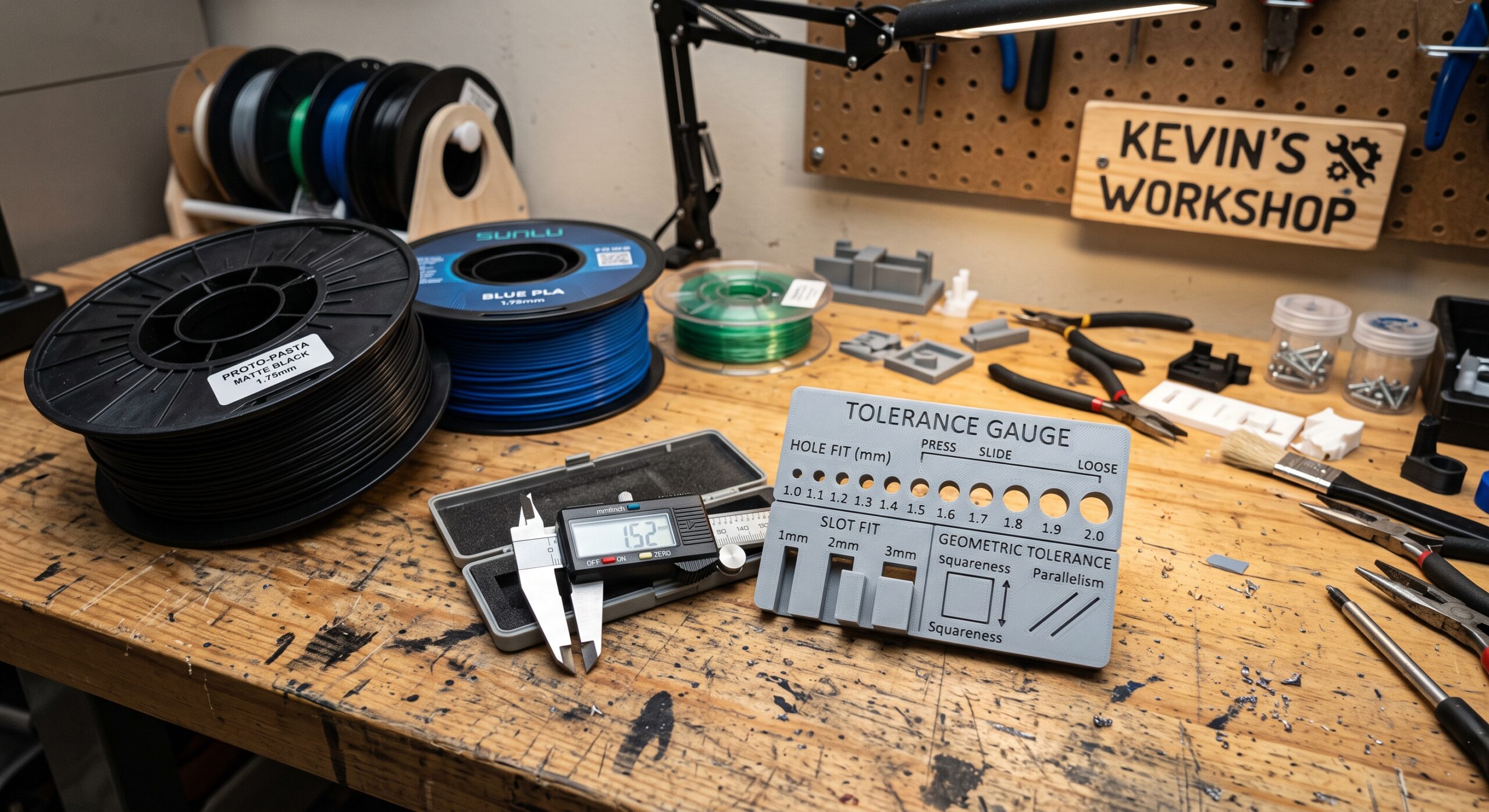
The most underrated 3D printed tool in my workshop is not a scraper holder, spool clip, or elaborate jig. It is a small 3D printed tolerance gauge—a plain-looking test part that tells me whether two pieces will actually fit before I commit hours and hundreds of grams of filament to the real job.
That answer matters whenever I am making a bracket, adapter, cap, guide, knob, organizer, prototype, or replacement part. A print can look perfect and still fail because one hole is tight, one peg rattles, or one first layer spreads just enough to stop assembly.
Quick Answer
A tolerance gauge is a compact test print containing labeled holes, pegs, slots, gaps, wall sections, or fit coupons. Print it with the same machine, nozzle, material, orientation, and profile planned for the final part. Then measure it and physically test the intended fastener or mating part.
The result is a local reference, not a universal formula. Change the material, nozzle, layer height, orientation, flow behavior, speed, or slicer compensation and the best-fit result may change with it.
Affiliate disclosure: This article contains a small number of relevant partner links. If you purchase through one, I may earn a commission at no extra cost to you. I include them only where they support a practical printing workflow.
Why a CAD Dimension Does Not Guarantee a Printed Fit
A CAD model is exact in a way melted plastic is not. During FDM printing, extrusion temperature, flow, velocity, layer thickness, cooling, shrinkage, first-layer compression, and toolpath choices can all influence the geometry that reaches your bench. NIST research on FFF dimensional accuracy likewise treats process parameters and uncertainty as part of the result—not background noise.
Even the shape matters. An outside wall, a vertical hole, a horizontal hole, a slot, and a surface touching the build plate do not necessarily show the same error. That is why one calibration cube cannot answer every fit question.
I work across machines including the Bambu Lab X1 Carbon, Raise3D Pro2, Creality CR-M4, and MakerGear M3. I do not assume that a result from one machine automatically transfers to another. The gauge belongs to the process combination: printer, nozzle, filament, profile, orientation, and feature geometry.
Technical context: NIST research on FFF process parameters and geometric accuracy.
What This Gauge Can—and Cannot—Tell You
| Question | Gauge can help? | What the result means |
|---|---|---|
| Which clearance gives a sliding fit? | Yes | Useful when the coupon matches the final material, orientation, and profile. |
| Will this exact screw enter the hole? | Yes | Test with the real fastener; nominal diameter alone is incomplete. |
| Is the printer mechanically healthy? | Partly | A changed result can reveal a problem, but the gauge does not identify every cause. |
| Will a snap-fit survive repeated use? | Partly | A snap coupon screens geometry and orientation; cycling and final-part testing still matter. |
| Will the finished part carry a safety-critical load? | No | That requires appropriate engineering, material data, process controls, and validation. |
| Can one number be used on every printer? | No | Tolerance is feature- and process-dependent; there is no universal desktop-FDM clearance. |
Prusa’s current design guidance makes the same central point: parts intended to fit together need tolerance, but the right amount depends on geometry, orientation, calibration, settings, material, and the kind of movement or retention required.
Design reference: Prusa’s official “Modeling with 3D printing in mind” guide.
Four Test Prints That Are Often Confused
Tolerance Gauge
Compares several clearances or sizes in one controlled print. Best for answering, “Which fit should I design?”
FitClearanceHole behaviorCalibration Cube
Offers a quick outside-dimension and surface check. Useful, but too simple to represent every internal feature or assembly.
Outside sizeSurface cluesTemperature Tower
Compares print behavior across temperatures. It can expose bridging, stringing, and surface changes but does not directly establish a final fit.
TemperatureSurface behaviorFinal-Geometry Coupon
Extracts the risky interface from the actual model. This is the strongest next step when a generic gauge cannot reproduce the real geometry.
Project-specificBest confirmationThe Fit Ladder: Test a Range, Not a Favorite Number
For a starter clearance ladder, I might model six labeled differences and learn from the complete series. The example below means the total difference between the outside dimension of one feature and the inside dimension of its mate—not the gap on each side.
These are test steps, not promised fit categories. A nominal 0.30 mm difference would create 0.15 mm of theoretical space per side only when the features are centered and the error is distributed evenly. Printed reality may not be that tidy.
How I Would Build a Useful 3D Printed Tolerance Gauge
Define the Fit Question
Decide whether you need a free-moving fit, a removable snug fit, a light press fit, a screw clearance, or a flexible snap. “Accurate” is not specific enough.
Match the Real Geometry
Test holes with the orientation they will have in the final part. Match wall direction, layer direction, depth, lead-in, corner shape, and mating material where possible.
Label Every Feature
Emboss or engrave the nominal size and clearly state whether a clearance value is total, diametral, radial, or per side. Ambiguous labels make a gauge nearly useless later.
Use the Real Profile
Keep the printer, nozzle, material, layer height, wall strategy, speed, temperature, flow, and compensation settings consistent with the planned job.
Print Beyond the First Layer
Include enough feature height to separate general fit from elephant-foot interference. A small bottom chamfer can help, but it should match the design strategy you will really use.
Record the Winner
Note the fit that worked, how it felt, what object was used to test it, and every relevant profile detail. A photo alone does not preserve the process.
The Measurement Routine That Makes the Gauge Valuable
Do not stop at “this one feels good.” A useful result combines measurement with function.
- Let the part cool completely. Do not measure a warm print or force a warm fit.
- Remove only obvious artifacts. If you sand or drill the coupon but not the real part, the comparison is no longer honest.
- Check the first-layer edge. If only the base binds, elephant foot may be the actual issue.
- Measure outside features gently. Calipers can flex thin walls or give false confidence when the jaws are tilted.
- Test with the real mate. Use the intended screw, shaft, cable, lid, bearing, or printed counterpart whenever possible.
- Describe the function. Record “slides under finger pressure,” “drops freely,” “holds upside down,” or “requires tools.” Those notes are more useful than “good.”
- Repeat a critical result. A second coupon helps distinguish a repeatable process from a lucky print.
Do Not Fix Every Fit Problem With One Slicer Offset
Modern slicers can compensate inside and outside contours. Bambu Studio, for example, separates XY hole compensation from XY contour compensation because internal and external boundaries may need different treatment. That separation is useful—but compensation should follow diagnosis.
If one feature family is wrong while the rest of the part is right, a targeted design or slicer adjustment may help. If every dimension changes from print to print, first investigate extrusion consistency, filament condition, mechanics, temperature stability, and profile choice. A global offset can hide one symptom while damaging dimensions that were already correct.
Start with the calibration trick that makes printers perform better, then use my reliable settings baseline. If the surface or dimensions remain inconsistent, work through the symptom-first troubleshooting guide.
Slicer reference: Bambu Studio’s official XY hole and contour compensation documentation.
When I Print a New Gauge
I do not print a new gauge for the sake of making plastic samples. I print one when the process combination changes enough that the old result may no longer answer the question.
| Change | Reprint? | Why |
|---|---|---|
| New printer | Yes | Motion, extrusion, cooling, and profiles differ. |
| New nozzle diameter | Yes | Line width and feature resolution change. |
| PLA to PETG, ASA, or TPU | Yes | Material behavior and shrinkage differ. |
| New functional-print profile | Usually | Layer height, walls, speed, flow, and compensation may affect fit. |
| Same material, different color | For critical fits | Pigments and formulations can change print behavior. |
| Routine maintenance with unchanged output | Not automatically | Use a known gauge as a verification print if something seems different. |
| Critical project geometry unlike the gauge | Print a project coupon | Final orientation and interface geometry matter more than a generic block. |
Use the Tolerance Gauge With the P.R.I.N.T. Method
The gauge is most valuable when it answers a question defined before printing.
Workshop record: project, date, printer, nozzle, filament brand/material/color, layer height, profile name, orientation, compensation settings, tested feature, winning fit, and notes.
Three Mistakes That Ruin Good Tolerance Data
Changing Several Variables
If you adjust flow, temperature, speed, and XY compensation together, the next result cannot tell you which change helped.
Using Different Orientation
A vertical test hole may not represent a horizontal hole with bridging or a surface formed against supports.
Saving the Plastic but Not the Data
An unlabeled gauge becomes desk clutter. Mark it and connect it to a profile or project note you can retrieve later.
Treating Feel as a Standard
“Snug” can mean something different tomorrow. Add a functional description and, when needed, a simple repeatable test.
Kevin’s Practical Rule
If the final part needs to fit something, I want the cheapest meaningful failure first. That might be a generic tolerance gauge, one extracted interface, or a short section of the final model. Twenty grams of useful evidence is better than a full-size print built on hope.
For consistent functional-print material, see COEX 3D filament and use code 3DPRINTINGBYKEVIN for 15% off.
Workshop Knowledge Check
Choose one answer for each question.
1. What makes a tolerance-gauge result transferable?
2. What does a 0.30 mm total diametral difference mean for centered round features?
3. One hole is tight, but every outside dimension is correct. What is the best next move?
4. What is the strongest final check for a critical interface?
Frequently Asked Questions
What is a 3D printed tolerance gauge?
It is a test part containing labeled variations of holes, pegs, slots, clearances, walls, or flexible features. It helps connect nominal CAD dimensions to the real fit produced by a specific printer, material, profile, orientation, and feature shape.
What clearance should I use for 3D printed parts?
There is no universal number. Begin with a small range that brackets the likely fit, label whether the value is total or per side, print under the intended conditions, and test with the real mating part. Fit type, size, orientation, geometry, material, calibration, and profile all matter.
Why do printed holes often come out tight?
Several effects may contribute, including extrusion behavior, polygonal model resolution, toolpath construction, first-layer spread, shrinkage, flow, and measurement technique. Diagnose the hole separately before altering correct outside dimensions.
Can a tolerance gauge replace printer calibration?
No. It reveals the output of the current process. If the result is inconsistent or visibly poor, calibrate or repair the underlying problem before using compensation to force a fit.
Should I make a separate gauge for PLA and PETG?
Yes when fit matters. Material behavior differs, and the print profiles probably do too. Label each gauge with the material and profile so results are not mixed later.
Do digital calipers make a tolerance gauge unnecessary?
No. Calipers measure geometry, while the gauge also tests function. Both matter. A part can measure close to nominal yet feel wrong because of local shape, texture, taper, orientation, or the mating component.
Can I use a tolerance gauge for safety-critical parts?
A hobby gauge alone is not adequate validation for safety-critical, structural, medical, protective, or regulated applications. Those uses require appropriate engineering controls, material traceability, testing, and applicable standards.
The Small Print That Protects the Big One
A tolerance gauge is valuable because it turns “I think this will fit” into evidence. It will not eliminate iteration, and it should not. It moves the learning to a smaller, faster, cheaper print where one correction is easy to understand.
That is how I approach practical 3D printing: measure the interface, test the uncertainty, record the result, and then commit to the full part.
What fit gives you the most trouble—holes, lids, pegs, snap-fits, or bearings? Share it in the comments. Your problem may become the most useful follow-up test for another maker.
