
Functional 3D printing • Failure diagnosis
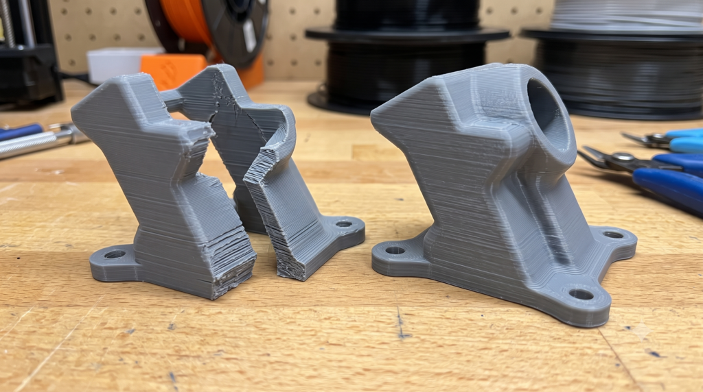
The break is evidence—do not bury it under more infill
A bracket snaps, a clip separates, or a holder splits into tidy horizontal layers. The reflex is to raise infill from 20% to 80% and print it again. That may add time and plastic without changing the load path that caused the failure.
Before touching the infill slider, study where the part broke, how the force reached that spot, and whether the material was bonding consistently. That short pause can separate a useful revision from a heavier copy of the same mistake.
Quick answer: Why did a 3D print break at the layer lines?
A clean split between layers usually points toward a combination of load direction, part orientation, geometry, extrusion consistency, temperature, speed, cooling, or material condition. More infill can help some load cases, but it cannot reliably repair weak interlayer bonding or a design that pulls directly across the layer stack. Start with the break pattern, preserve a known-good profile, and change one controlled variable at a time.
Affiliate disclosure: This article may contain affiliate links. If you make a qualifying purchase through one of these links, 3D Printing by Kevin may earn a commission without adding a separate charge to your purchase. Recommendations are selected for their relevance and potential usefulness to the reader.
First, read the fracture
Do not throw the failed part away. Place the pieces back together and look at the surface where they separated. A fracture is not a complete diagnosis, but it gives you a better starting point than a random settings change.
A flat, layer-shaped split
The load may be pulling across the Z direction, or the roads may not have fused consistently. Check orientation, temperature, cooling, speed, flow stability, and material condition.
A crack at a hole or sharp corner
The geometry may be concentrating stress. Look at edge distance, wall thickness, inside radii, fastener load, and whether the hole sits on a seam or thin section.
A part that bent before it broke
Material stiffness, heat, sustained load, wall design, or leverage may matter more than infill percentage. Document the operating environment before choosing the next material.
Kevin’s shop rule
Preserve the failed part, the sliced file, and the profile that produced it. If you change the model, filament, orientation, temperature, fan, speed, walls, and infill at once, the next print may improve—but you will not know why.
More infill versus a stronger plan
Infill supports top surfaces and can contribute to stiffness and load distribution. It is not a universal strength control. For many functional shells, wall count and geometry carry a large share of the useful load. Prusa’s current slicer documentation likewise notes that model strength is primarily influenced by the number of perimeters rather than infill.
| Change | When it may help | What it cannot prove | Better first question |
|---|---|---|---|
| Increase infill | Crush resistance, broad surface support, local stiffness, or loads that truly engage the interior | That layers are bonding well or the part is oriented for the applied force | Did the fracture travel through the interior, or peel between layers? |
| Add walls | Shell-dominated brackets, holes, edges, bending loads, and thin functional features | That a sharp corner, poor layer bond, or unsafe application has been corrected | Where does the load enter and leave the part? |
| Change orientation | Reducing tension or peeling across layer interfaces and aligning roads with important loads | That support surfaces, accuracy, finish, or every secondary load will improve | Which direction will try to separate the layers? |
| Change material | Heat, weather, impact, flexibility, wear, or stiffness requirements | That the geometry, printer setup, and process are appropriate | What property did the old material lack? |
| Raise temperature or slow down | When the current profile is not melting and depositing the material consistently enough | That hotter or slower is always better; excess heat can create other defects | Does the manufacturer’s profile or a controlled test support the change? |
Technical reference: See Prusa Research’s current guidance on layers and perimeters. Treat any slicer manufacturer’s recommendation as a starting point for its own software and validate the real part.
Use the P.R.I.N.T. Method™ before the reprint
The P.R.I.N.T. Method keeps the investigation attached to the job the part must do. It is especially useful here because a fracture can be a design problem, a process problem, a material problem—or more than one at the same time.
Orientation: put the layer stack where it can survive
FFF parts do not behave identically in every direction. The deposited roads, their direction, and the bonds between layers create an anisotropic part. Research continues to show that build orientation can materially change tensile behavior, but the size of that effect depends on the tested material, geometry, raster strategy, machine, and process.
For a hook, tab, bracket, or lever, sketch the expected force as an arrow. Then ask whether that arrow tries to pull two printed layers apart. If it does, consider rotating the part, splitting and joining the design differently, widening the load path, adding a radius, moving a seam, or using hardware to carry the load.
Do not optimize only for the strongest-looking axis
Orientation also changes support needs, hole shape, surface finish, dimensional accuracy, print time, and the direction of secondary loads. The best orientation is the one that balances the part’s real requirements—not the one that wins a single test coupon.
Fact-check reference: This 2025 open-access study examines how printing orientation affected tensile strength and surface roughness in its defined material and test conditions. Its results should not be treated as a universal percentage for every printer or part.
When the problem is the bond, not the model
A well-oriented part can still separate if the extrusion process is unstable. Begin with the validated profile for the exact printer, nozzle, build plate, and filament. Then inspect the basics before inventing a new recipe.
- Confirm the profile. Make sure the selected machine, nozzle diameter, filament, and plate match the hardware on the bench.
- Inspect the filament path. Look for drag, tangles, a partial clog, a damaged nozzle, extruder slipping, or inconsistent feeding.
- Check material condition. Moisture sensitivity differs by polymer and environment. Follow the filament maker’s storage and drying directions instead of applying one temperature and time to every spool.
- Review temperature and cooling together. A layer needs enough heat and time to bond, but excessive heat can reduce detail, increase sag, or create other problems. Cooling needs also vary by material and geometry.
- Check throughput. A printer can move faster than its hotend and material can melt consistently. If weak bonding appears mainly at higher speeds, compare a conservative baseline before changing flow compensation.
- Use an interface-specific test. Print the hole, tab, hinge, corner, or layer direction that matters. A decorative benchmark may not reproduce the failure.
Prusa’s current maximum-volumetric-speed documentation lists under-extrusion and poor layer adhesion among the signs that requested throughput is too high. The useful lesson is not a universal speed number; it is to keep the melt capacity of the hotend and material ahead of the commanded extrusion.
Technical reference: Prusa Research: Maximum volumetric speed.
Wall design can beat a brute-force infill change
Imagine a mounting hole placed close to the edge of a two-wall bracket. Raising infill may add plastic behind the walls, yet the thin ring around the hole can remain the first place to crack. A more useful revision might add wall thickness, move the hole, increase edge distance, add a washer or insert, round the inside corner, widen the bracket, or change how the load enters the part.
That is why the model and the slicer should be reviewed together. The slicer preview can reveal thin sections, gaps between walls, sparse material around holes, abrupt line starts, seam locations, unsupported features, and places where the intended reinforcement did not become an effective toolpath.
If the part must fit an existing assembly, begin with How to Measure a Part for 3D Printing. Correct reinforcement in the wrong location is still the wrong part.
Tap-to-check workbench tool
P.R.I.N.T. failure planner
Use this planner before starting the next print. Tap the boxes on screen, or print the page and mark it by hand. The selections are not submitted or saved.
1. Where did the failure begin?
2. What load was present?
3. What evidence did you preserve?
4. Choose one first test
5. Record the result
One variable changed:
What improved or worsened:
Next justified step:
Where material choice fits
A different polymer can be the right answer when the requirements call for more temperature resistance, outdoor durability, impact behavior, flexibility, or stiffness. It is not a substitute for fixing a concentrated load or unreliable extrusion.
If inconsistent material is part of the investigation, compare one known spool using a validated profile and keep the test small. I have discussed why repeatability matters in The Filament Brand I Keep Coming Back To. Readers who want to evaluate Kevin’s U.S.-made filament partner can browse COEX 3D filament and enter partner code 3DPRINTINGBYKEVIN at checkout to see whether the current order qualifies for a discount. Choose the polymer for the job, not for the coupon.
A practical 20-minute diagnosis before a long reprint
- Photograph the fracture. Capture the break surface, installed direction, nearby fasteners, and the direction of force.
- Open the sliced file. Inspect walls, seams, thin sections, infill contact, speed or flow preview, and the exact layer where the failure began.
- Confirm the baseline. Check the printer, nozzle, plate, filament profile, and material condition.
- Cut the model. Print only the critical hole, clip, corner, or wall section when possible.
- Change one variable. Orientation, geometry, walls, or a justified process setting—not all of them.
- Test in the real direction. Mark the sample, apply a controlled load, and record what changed.
Need a structured reference beside the printer? P.R.I.N.T. It: Practical 3D Printing for Beginners includes the first-print checklist, troubleshooting chart, maintenance log, and the complete P.R.I.N.T. Method™. Use the planner above to capture this failure, then carry the result into the ebook’s repeatable troubleshooting workflow.
Quick knowledge check
Open each question to test the decisions that matter before the reprint.
1. A bracket split cleanly between layers. What should you inspect before raising infill?
Inspect the load direction, print orientation, geometry, profile, filament path and condition, temperature, cooling, speed, and extrusion consistency. Infill is only one variable and may not address the layer interface that failed.
2. Why can adding walls help more than adding infill?
Many brackets, holes, edges, and bending features carry significant load through the outer shell. More walls or local model thickness may place material directly in that load path, while extra interior infill may not reinforce the critical feature.
3. Should you copy one “strongest orientation” rule for every part?
No. Orientation affects layer loading, supports, surface finish, hole quality, dimensional accuracy, print time, and secondary forces. Choose it from the complete set of requirements and verify the real interface.
4. Why change only one variable during a controlled test?
One change creates evidence you can interpret. Changing the model, material, temperature, cooling, speed, walls, and infill together makes it difficult to identify what actually improved—or damaged—the result.
Frequently asked questions
Is 100% infill the strongest setting?
Not as a universal rule. Dense infill can increase stiffness and strength in some load cases, but geometry, wall count, orientation, layer bonding, material, and process consistency may matter more. It also adds time, material, heat buildup, and weight.
Does a higher nozzle temperature always improve layer adhesion?
No. Too little heat can reduce bonding, but excessive temperature can increase sag, stringing, discoloration, dimensional change, or material degradation. Start with the current manufacturer profile and use a controlled temperature test only when the symptom justifies it.
Can too much cooling make a functional part weaker?
It can reduce interlayer bonding for some materials and geometries, but cooling also supports overhangs, bridges, and shape control. The correct fan strategy depends on the polymer, printer, layer time, feature, and manufacturer guidance. Read Why Your 3D Print Cooling Fans Might Be Too High for the symptom-first approach.
Will drying filament fix every weak-layer problem?
No. Drying can help when moisture is contributing to inconsistent extrusion, but it will not correct poor orientation, a sharp stress riser, a partial clog, an unsuitable profile, or the wrong material. Follow the filament manufacturer’s drying limits.
Should I make a safety-critical replacement part stronger and try again?
Do not treat a stronger-looking print as proof of safety. Parts involving personal support, fuel, flame, pressure, high voltage, braking, medical use, certification, or severe consequences of failure may require qualified engineering review, validated testing, another manufacturing process, or a decision not to print them.
What should I send Kevin for a broken-part review?
Send clear photos of the part and assembly, both broken pieces, critical dimensions, the material if known, the direction and type of load, operating heat or weather, quantity, and any STL, STEP, OBJ, drawing, or sliced project file you have. Start with the Quote / Project Intake page.
Keep learning beyond one fix
For additional design exercises and 3D-printing education, explore Maker’s Muse. External tutorials can broaden your options, but validate any recommendation on the specific printer, material, geometry, and real use in front of you.
The goal is not a heavier reprint—it is a better load path
When a part fails, the fastest-looking fix is often to add plastic. The more useful fix is to understand the problem, document the requirements, inspect the interfaces, select the next-best change, and test it deliberately.
When replacement parts disappear, we make the next one. When a printed part breaks, we use the evidence to make the next version smarter.
Practical-use note: Printed-part performance depends on the model, material, orientation, machine, profile, environment, load, manufacturing consistency, and test method. A successful print is not automatic proof that a part is safe or suitable for a critical application.
