
3D Printing by Kevin | Replacement Parts Guide
The broken clip is only two inches long. You measure it, model it, and print a replacement that looks almost perfect. Then you try installing it. The screw holes miss. The tab won’t slide into its slot. Or worse, it fits once and snaps when you remove it.
That’s a frustrating way to spend an evening—and a surprisingly common way to waste filament.
Here’s the catch: the printer may have done exactly what you told it to do. The measurements were wrong before the first layer went down.
Learning how to measure a broken part for 3D printing means more than copying its length and width. You have to identify which dimensions still represent the original design, which were changed by damage or wear, and how the replacement will fit the surrounding assembly.
I’ll walk you through a seven-step process that works for many brackets, clips, covers, spacers, and small mechanical replacements. You don’t need advanced CAD experience to start.
Quick Answer
How do you measure a broken part for 3D printing?
Start by photographing the broken part and identifying how it worked. Measure its undamaged reference surfaces, then measure the object it attaches to. Record critical holes, shafts, tabs, thicknesses, and mounting distances using digital calipers where practical.
Reconstruct missing geometry from symmetry or mating components, allow for the required fit, and print a small test section before producing the whole replacement.
Kevin’s workshop rule: Measure what the new part must fit—not just what remains of the old part.
The seven-step plan: from broken plastic to a better replacement
There is a much easier way to approach reverse engineering than measuring dozens of random surfaces and hoping the CAD model works.
Follow this sequence:
Inspect 2
Identify 3
Measure 4
Rebuild 5
Allow 6
Test 7
Record
Inspect the break before touching the calipers
Before cleaning the part or discarding any fragments, find out why it failed.
A cracked bracket and a worn gear may both need replacements, but they tell very different stories. One may have failed under bending stress. The other may have gradually worn because its teeth did not mesh correctly.
Look for these clues:
- Crack at a sharp inside corner: possible stress concentration. A rounded transition may help.
- Thin wall that split: investigate load direction, wall thickness, aging, and material behavior.
- White stress marks around a clip: possible excessive deflection or repeated bending.
- Heat-distorted shape: the original dimensions may be unreliable.
- Rounded contact surfaces: wear may have changed the original fit.
A broken feature tells you where to investigate—not necessarily the complete cause of failure. Avoid automatically blaming wall thickness or filament choice.
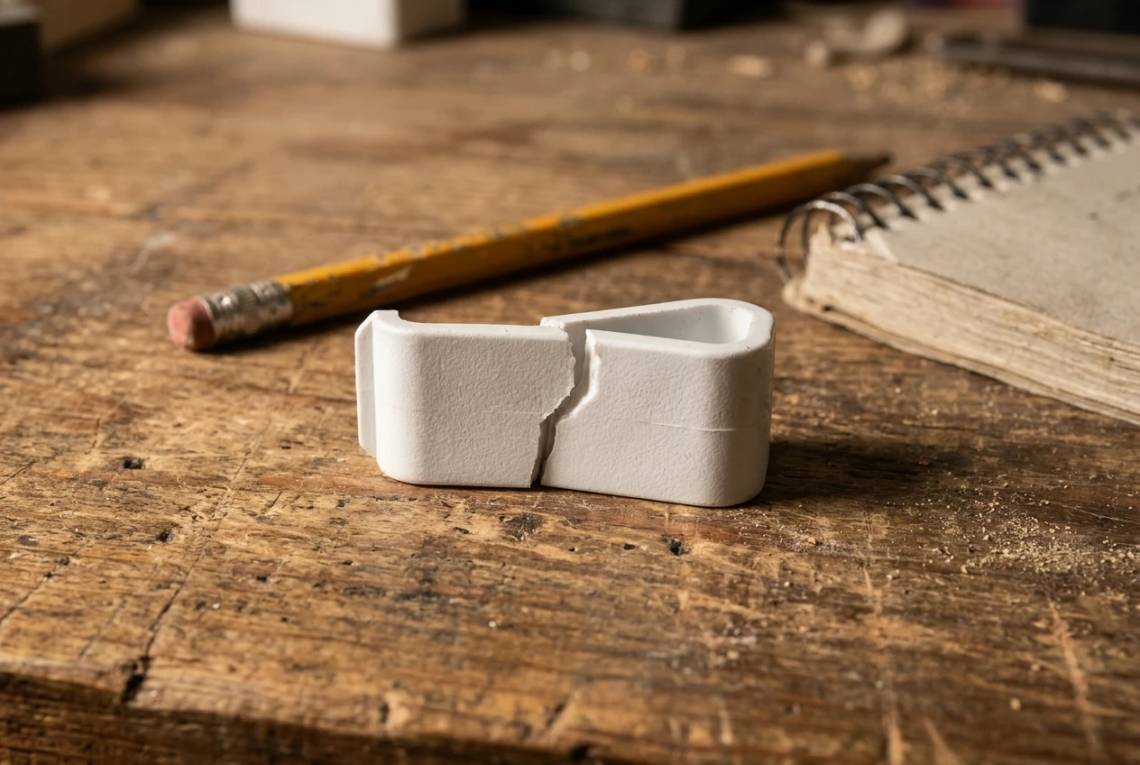
Photograph the broken part from the top, bottom, front, back, and both sides. Include the mounting area and any surviving fragments. A ruler in the same plane can help provide scale, although photographs alone cannot establish precision dimensions.
Identify the surfaces that actually control the fit
Here’s a common mistake: spending twenty minutes measuring the decorative outside shape while overlooking the two holes that must align with an existing mounting bracket.
Instead, identify the functional interfaces—the places where the replacement touches, fastens, slides, rotates, snaps, or locates against something else.
Position
Mounting holes, locating pins, shoulders, stops, and reference faces.
Movement
Sliding tabs, gear shafts, hinges, channels, and rotating surfaces.
Retention
Snap clips, screw seats, locking edges, and press-fit features.
Clearance
Nearby housings, covers, cables, fasteners, and moving mechanisms.
Then measure the mating part. If the replacement must fit a metal shaft, measure the shaft. If it attaches to two threaded holes, measure those mounting locations. If it slides into a plastic channel, measure the channel’s usable width and depth.
The mating assembly is often a better reference than a worn or deformed original. It must still be inspected for damage of its own.
Measure carefully, then measure again
Start with the overall dimensions so you understand the part’s size. Next, move to its functional features.
For each critical measurement:
- Choose a stable, undamaged reference surface.
- Zero your calipers and verify the jaws are clean.
- Keep the measuring jaws square to the feature.
- Use gentle, consistent pressure, especially on flexible plastic.
- Repeat the reading and compare results.
- Record both the dimension and how confident you are in it.
Don’t average together measurements from visibly worn and unworn surfaces as though they describe the same original geometry. Record their differences and investigate.
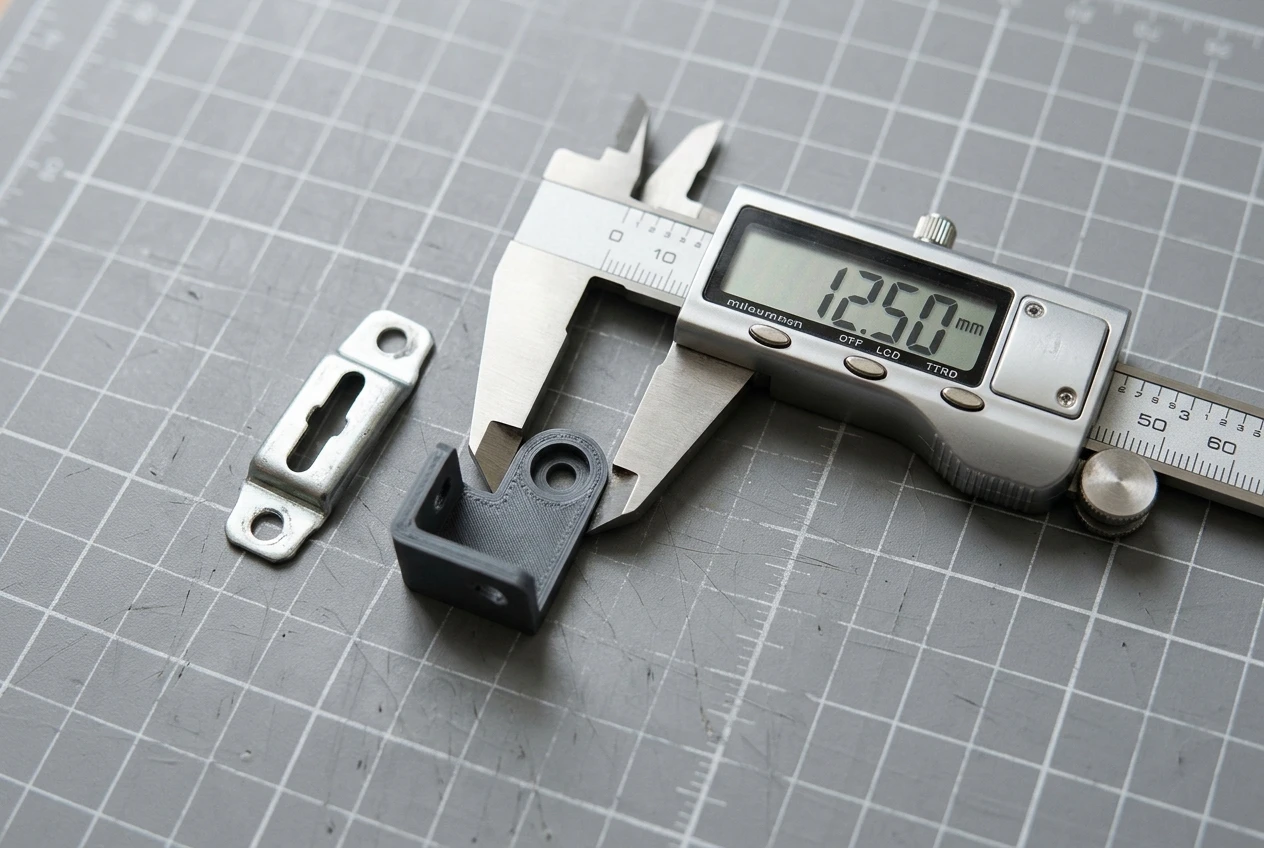
The measuring tools you actually need
| Tool | Best use | Important limitation |
|---|---|---|
| Digital calipers | Outside sizes, inside widths, depths, step dimensions | Display resolution is not guaranteed measurement accuracy |
| Steel ruler | Overall size and approximate layout | Not suitable for close mechanical fits |
| Drill bits or pin gauges | Checking whether a hole accepts a known diameter | Use measured shanks or proper gauges; do not force them |
| Small square | Checking straightness and perpendicularity | Does not by itself establish exact angular geometry |
| Phone camera | Documenting orientation, fracture evidence, and assembly | Perspective can distort apparent dimensions |
Why a 0.01 mm caliper reading isn’t automatically accurate to 0.01 mm
Many digital calipers display measurements in increments of 0.01 mm. That’s resolution—not a promise that every measurement is correct to the nearest hundredth of a millimeter.
Instrument quality, calibration, jaw alignment, technique, and the shape of the feature all affect accuracy. Even precision measuring tools require appropriate use.
Read Mitutoyo’s explanation of caliper accuracy and measurement technique.
How to measure the distance between two holes
Hole spacing is one of the easiest dimensions to get wrong, especially when the original part is cracked between mounting points.
For two equal circular holes arranged along a straight line, measure from the far outside edge of the first hole to the far outside edge of the second. Then subtract the diameter of one hole.
Worked Example
Outside-to-outside span: 30.0 mm
Hole diameter: 5.0 mm
Center-to-center spacing: 30.0 − 5.0 = 25.0 mm
For different hole diameters, subtract half of each diameter from the far outside-edge span. This assumes the measured edges align with the line connecting the hole centers.
If the mounting holes are worn, oval, or inaccessible, measure the mating fastener positions and reference geometry instead. A rough hole-edge measurement may not support a precision replacement.
Reconstruct the missing geometry without copying the damage
What happens if the tab you need to measure isn’t there anymore?
Fortunately, the missing piece often leaves clues:
- Symmetry: An intact matching feature on the opposite side may provide a useful reference.
- Matching parts: A left-hand or right-hand version may reveal the intended design.
- Mounting geometry: The mating slot, shaft, screw pattern, or housing can establish the space available.
- Remaining fracture surfaces: Surviving pieces can reveal wall thickness, profile, and length.
- Product photographs or drawings: These may clarify the original arrangement when the fragment is missing.
Sketch the component before opening CAD. Mark which measurements are observed directly, which are derived from other dimensions, and which are still estimates.
If an estimate affects fit or safety, don’t quietly treat it as a proven dimension. Validate it with a test section or additional measurement.
Should you use a 3D scanner?
A scanner can help with complex contours and freeform surfaces, but it does not automatically recover a broken-off feature or determine the correct mechanical clearance. Simple brackets and clips are often easier to reconstruct from dimensions and an editable CAD model.
For a broader measurement workflow, read How to Measure a Part for 3D Printing: 7 Steps for a Better Fit.
Understand clearance before expecting the replacement to fit
This is where an accurate measurement can still produce a badly fitting part.
Imagine a steel pin measures 12.00 mm. You model a printed hole at exactly 12.00 mm, expecting it to slide over the pin. But real printed dimensions may differ from CAD dimensions because of extrusion behavior, cooling, orientation, and the first layer.
Even if both components were exactly 12.00 mm, a zero-clearance sliding joint would leave no intentional room for movement.
Dimensional accuracy
How closely the manufactured part matches the CAD dimension.
Tolerance
How much a dimension may vary while the component still meets its requirements.
Clearance
The space intentionally provided between mating components.
Fit
How the components actually assemble, move, locate, or grip each other.
For a circular pin inside a circular hole, subtracting the pin diameter from the hole diameter gives the total diametral clearance. Divide that result by two to obtain the nominal radial gap on each side when the pin is centered.
Interactive Tool
Try the fit-gap calculator
Enter the measured pin and hole diameters to see their nominal clearance. These numbers illustrate the geometry; they don’t predict whether an FDM print will actually fit.
Nominal radial gap per side: 0.15 mm
These values assume the centered, measured geometry.
Positive clearance indicates a geometric gap; zero means nominal line-to-line contact; negative values indicate interference. Real fit also depends on shape, texture, material, and measurement uncertainty.
For actual design guidance, read 3D Printing Tolerances Explained: Why Parts That Look Perfect Still Don’t Fit.
Prusa’s official modeling guide also explains why no single clearance value works for every printer, material, and orientation.
A loose cover, snap-fit clip, sliding rail, and rotating shaft require different fit behavior. A small coupon using the final material and print orientation is a more dependable starting point than a universal number copied from the internet.
Print the feature that matters—not the entire replacement
Suppose you’ve rebuilt a bracket that takes six hours to print. Its whole purpose depends on a single small hole accepting a mounting pin.
Why print six hours of plastic to find out whether that one hole fits?
Make a test coupon containing just the relevant interface. For a hole, print a small plate with several candidate diameters. For a snap clip, print a representative section that includes the beam, root, and engagement geometry.
A useful sequence looks like this:
- Model the critical interface and its surrounding support geometry.
- Use the intended material, nozzle, orientation, layer height, and relevant process settings.
- Print the small test section and let it cool.
- Measure the printed feature and try it in the actual assembly without excessive force.
- Record whether the fit is tight, loose, misaligned, or just right.
- Adjust one variable at a time and repeat where needed.
If the coupon tests only a rigid hole dimension, you may simplify noncritical geometry. If it tests bending strength or snap engagement, preserve the actual relevant wall sections, infill, and geometry.
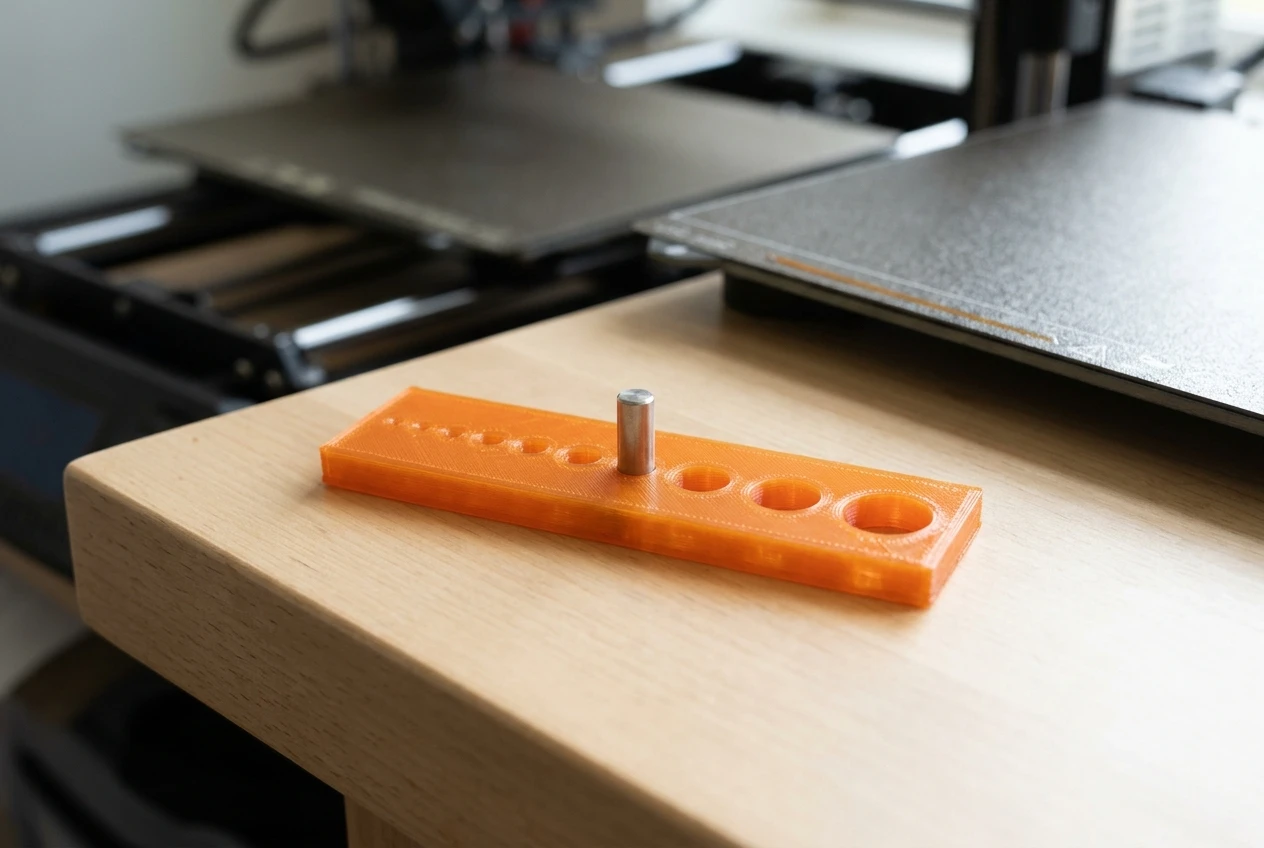
My rule for test prints
Don’t judge a prototype only by whether you can force it into place.
Check alignment, insertion and removal force, movement, interference with surrounding parts, and whether the joint still performs its intended function.
Then read Why 3D-Printed Replacement Parts Need a Test Fit for the next part of the workflow.
Save the measurements that made the replacement work
Once you have a working part, your notes become valuable. A later repair or second production run should not require starting from scratch.
Save the CAD model and create a small project record with:
- Part name, revision, and date
- Overall dimensions and critical interface measurements
- Which surfaces were damaged or estimated
- Required fit and successful clearance adjustments
- Filament and relevant print settings
- Test results and any remaining limitations
- Photos of the finished part installed in the assembly
If your first replacement needed a 0.20 mm hole adjustment, record what you changed and whether the number refers to the CAD diameter, printed diameter, or clearance. That distinction will matter later.
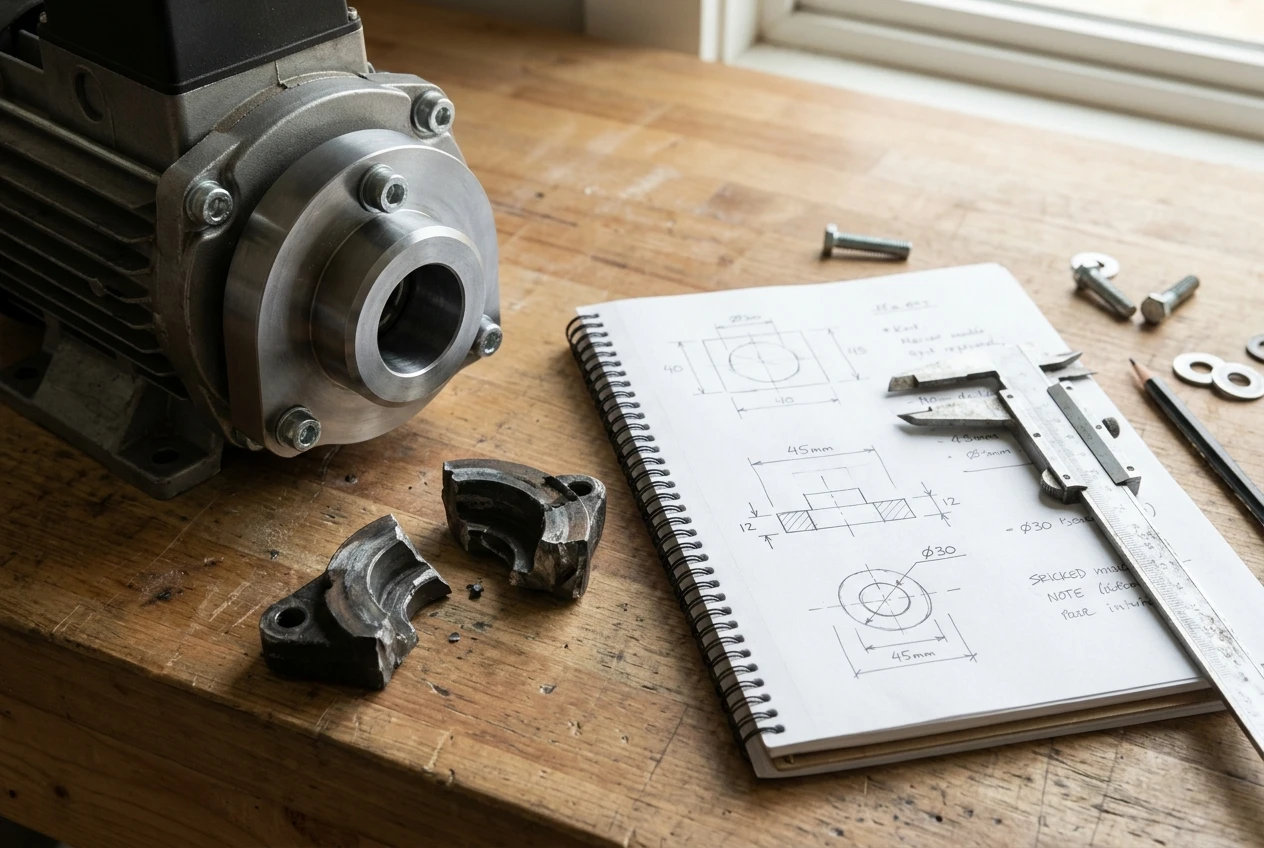
Measurement mistakes that waste the most filament
| What goes wrong | Why it fails | Better next step |
|---|---|---|
| Measuring a warped edge | The dimension may reflect damage rather than the original shape | Use undamaged datums or mating geometry |
| Copying the worn hole | Wear may have enlarged or distorted the opening | Check the fastener, shaft, or corresponding feature |
| Measuring only once | Jaw angle or pressure may create a misleading reading | Repeat and document variation |
| Assuming caliper resolution equals accuracy | The instrument and method have measurement uncertainty | Check tool specifications and confirm critical dimensions |
| Modeling exact nominal sizes | The fit may need intentional clearance or interference | Build and test the required joint behavior |
| Printing the whole part first | A tiny fit error wastes hours of printing | Isolate the critical interface and test it |
| Copying the original weak feature | The same stress concentration may cause another failure | Evaluate material, orientation, and practical redesign |
DIY measurement or professional reverse engineering?
Many small replacement projects are within reach of someone with calipers, a little patience, and basic CAD skills. But the right approach depends on how difficult the geometry is and what happens if the new part fails.
DIY may be appropriate when:
- The geometry is relatively simple.
- Critical mounting features are accessible.
- The consequences of a poor fit are minor.
- You can print and test prototypes safely.
Consider professional help when:
- Important features are missing or badly worn.
- The replacement must fit several interfaces.
- You need multiple consistent copies.
- You lack CAD tools or measurement access.
A safety check before recreating a broken component
Disconnect and isolate equipment before inspecting moving mechanisms, powered assemblies, or hot surfaces. Don’t substitute an unverified hobby-printed part for a safety-critical, pressure-containing, high-temperature, or heavily loaded component.
Such projects may require qualified engineering evaluation, controlled materials, and validation beyond a basic fit test.
When replacement parts disappear, we make the next one.
Have a broken plastic part you’d rather not measure and model yourself?
At 3D Printing by Kevin in Northern Kentucky, I help individuals and businesses explore practical custom replacements, discontinued parts, prototypes, fixtures, and small-batch projects.
You don’t need a finished STL file to start. Clear photographs, surviving fragments, approximate dimensions, and a description of what the part needs to do are useful for an initial review.
I’ll help determine what additional information is needed and whether FDM 3D printing is a suitable option for your application.
Request a Custom 3D Printing QuoteQuick measurement checklist: what to send with a project
Use this checklist whether you’re preparing your own CAD model or submitting a replacement-part request.
- ☐ Photograph all sides of the damaged part.
- ☐ Include photos showing where it installs.
- ☐ Keep the original fragments when possible.
- ☐ Record overall length, width, height, and thickness.
- ☐ Measure holes, slots, tabs, and mounting distances.
- ☐ Measure accessible mating features.
- ☐ Mark missing or distorted geometry.
- ☐ Explain how the part broke and what loads it handles.
- ☐ Note exposure to heat, sunlight, moisture, or chemicals.
- ☐ Identify features needing a test fit.
No calipers yet? You can still begin with clear photographs, a ruler, and a useful description. More precise measurements may be needed later.
Four-question knowledge check
Let’s see whether you can catch the mistakes that send replacement prints back to the drawing board.
Frequently asked questions about measuring broken parts
Can a broken plastic part be measured accurately enough to reproduce?
Often, yes, if enough useful geometry survives or if the mating assembly provides reference dimensions. The feasibility depends on missing features, wear, required fit, available tools, and the consequences of failure. Some jobs require controlled prototypes or professional measurements.
Do I need digital calipers to replace a broken plastic part?
Not always. A steel ruler and photographs may be enough for an initial assessment or a low-precision cover. Digital calipers are especially helpful for holes, shafts, slots, wall thicknesses, and mechanical interfaces.
What if the most important piece is missing?
Check the surrounding assembly, matching features, symmetry, original hardware, diagrams, and surviving fragments. The missing geometry may need to be reconstructed in CAD and validated through a small test print.
How much clearance should I add to a 3D printed replacement?
There is no universal value. The correct amount depends on the intended fit, material, printer, orientation, dimensions, and manufacturing behavior. Use a representative test coupon and distinguish total diametral clearance from the gap per side.
Can I measure a broken part from photographs alone?
Photographs can help estimate shape and scale, but perspective, lens distortion, camera angle, and hidden geometry limit their reliability. Use direct measurements for critical mating features whenever practical.
Should I recreate the original part exactly?
Not necessarily. If a thin root, sharp corner, unsuitable material, or poor fastener arrangement contributed to failure, consider a practical redesign while preserving the dimensions required to fit the existing assembly.
The goal isn't to copy the broken plastic. It's to restore the function.
A replacement doesn't have to be a perfect visual duplicate to be successful. It has to locate correctly, fit the assembly, withstand the intended use, and avoid repeating preventable failures.
Sometimes the difference is a small clearance adjustment. Sometimes it's a stronger fillet at a stressed corner. Sometimes you simply have to measure the mounting bracket instead of the broken clip.
The next time a plastic part breaks, don't begin with the printer. Begin with the evidence.
Tell me in the comments: What's the hardest part you've had to measure—a broken clip, stripped gear, missing bracket, or something even more unusual? What was the feature that made it difficult?
Further reading and technical references
- 3D Printing Tolerances Explained — 3D Printing by Kevin
- Why Replacement Parts Need a Test Fit — 3D Printing by Kevin
- Broken Brackets and Clips Replaced with 3D Printing
- Prusa: Modeling With 3D Printing in Mind
- Formlabs: Understanding Engineering Fits
- Mitutoyo: Caliper Accuracy and Measurement Techniques
Editorial note: Numerical examples illustrate fit geometry, not guaranteed FDM tolerances. Real manufacturing outcomes depend on machine setup, material, part geometry, orientation, measurement quality, and operating conditions. No high-consequence application should be validated solely by an informal fitting test.
Affiliate disclosure: Some links elsewhere on 3D Printing by Kevin may earn a commission from qualifying purchases at no additional cost to the customer. This guide prioritizes measurement education and the custom-service intake process; it does not contain an unverified shopping link.
