
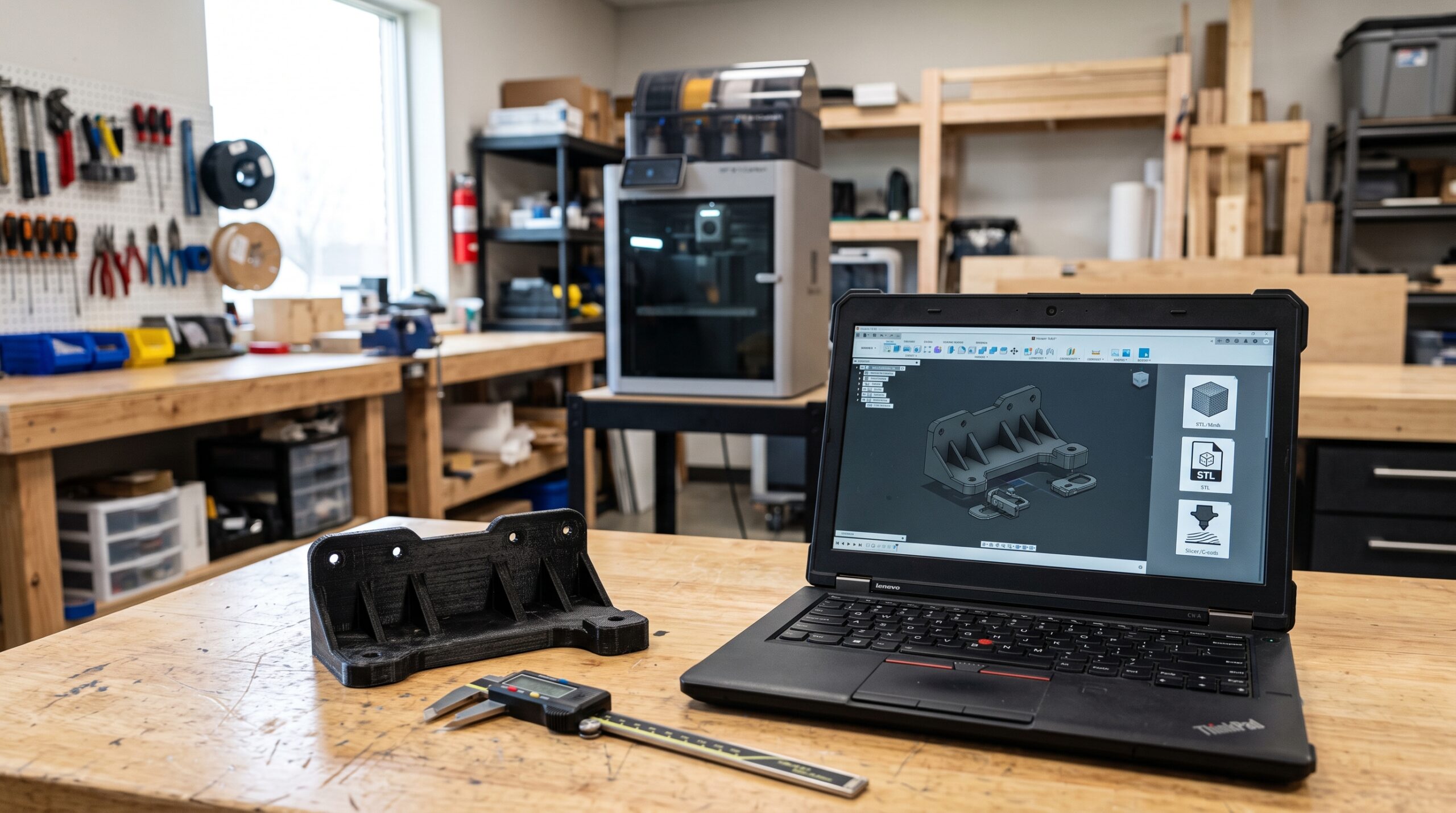
A practical custom-part file guide
You have a model on your computer and a part you want made. The natural next step seems simple: attach the file and request a quote. But the file you send affects what can be checked, changed, scaled, repaired, and prepared before the first layer is printed.
An STL can be perfectly suitable when the geometry is finished. A STEP file is usually more useful when a hole, wall, fillet, or mounting feature may need to change. A 3MF can preserve more print-oriented information than STL. An OBJ may make sense for a textured scan or artistic model. And if you have no file, clear photos, measurements, and the broken original may be the most honest starting point.
Quick answer: Which 3D printing file should you send?
Send a STEP file when the part may need mechanical edits, an STL or 3MF when the geometry is finished and ready for print preparation, and an OBJ when surface color or texture matters. If possible, send the editable CAD file plus an STL or 3MF preview. Do not send G-code unless the printer, nozzle, material, build plate, and profile have already been agreed upon. If you have no digital model, send photos, measurements, a sketch, and a plain-language description of what the part must do.
The file is only one part of the project
A model can describe a shape without explaining its job. It may not reveal whether the part lives in a hot vehicle, flexes every day, supports a static load, clips into another component, or needs 135 repeatable copies. It also may not show which dimensions are critical and which surfaces are merely cosmetic.
This is why I do not begin a practical custom-part review by asking only, “Can the file be opened?” I also want to know what the part must accomplish, how it connects, where it will be used, what happens if it fails, and how many are needed. The file supports those answers; it does not replace them.
A useful two-file handoff
If you designed the part in CAD, a strong handoff is often the editable or neutral CAD file plus a print-ready reference file. For example, send STEP for revision and STL or 3MF for comparison. Add a PDF drawing or marked-up screenshot when specific dimensions, hole locations, or appearance requirements must not be misunderstood.
STL vs. STEP vs. 3MF vs. OBJ at a glance
| Format | What it mainly carries | Strongest use | Main limitation |
|---|---|---|---|
| STL | Triangulated surface mesh | Finished geometry for broad slicer compatibility | Harder to revise as precise mechanical CAD; scale can be misread |
| STEP | Exchangeable product and CAD geometry | Mechanical parts that may need dimensional or feature edits | Not normally the final file sent directly to the printer |
| 3MF | Mesh geometry, defined units, metadata, and optional print-project information | Print-oriented handoff, multi-body work, and slicer projects | Saved settings and extensions are not interpreted identically by every application |
| OBJ | Mesh geometry with basic material and texture support | Scanned, artistic, colored, or textured surfaces | Less convenient than solid CAD for precise mechanical revisions |
| G-code | Printer movement, temperature, extrusion, and process commands | An already-approved, machine-specific print job | May be incompatible or unsafe on a different printer or hardware setup |
When an STL file is enough
STL remains one of the most common ways to move a finished model into a slicer. It represents the surface with triangles. As Autodesk’s STL documentation explains, exporting a solid to STL translates that geometry into a faceted mesh.
That makes STL practical when the design is finished, the scale is confirmed, and the goal is to orient, support, slice, and print the model. It is widely recognized, relatively simple, and suitable for many brackets, organizers, prototypes, props, and replacement parts.
Send STL when the shape is final and you mainly need print preparation—not feature-level design work.
Where STL creates extra work
A triangle mesh is not the same as the original CAD model. Moving a hole, changing a wall thickness, removing a fillet, or rebuilding a snap feature can be much more awkward after the solid geometry has been converted to triangles. A low-resolution STL can also turn smooth curves into visible flats, while an unnecessarily dense mesh can create a large file without improving what the printer can reproduce.
Scale deserves special attention. STL workflows can interpret units differently. Shapr3D’s own STL unit guidance warns that a model made in inches can arrive incorrectly when the slicer assumes millimeters. Include at least one known dimension in your message or drawing so the received model can be checked.
Why STEP is often better for a mechanical part
STEP is designed for exchanging product data between computer systems. The ISO 10303 overview describes a framework for representing and exchanging product information across design, manufacturing, use, and other stages of the product lifecycle.
In everyday custom-part work, the practical advantage is editability. A STEP model usually gives the designer more useful geometry for changing a hole diameter, extending a boss, thickening a wall, splitting an oversized part, or adjusting a mounting surface than a triangulated STL does.
Send STEP when fit, interfaces, or mechanical features may still change—or when you want to preserve a cleaner path for future revisions.
STEP does not automatically include the full feature history from the original CAD application, and not every imported model behaves perfectly. The native design file may still be the best revision source when both parties use compatible software. But STEP is a strong neutral handoff for mechanical geometry. Shapr3D’s current export guide, for example, separates 3D-model exchange formats such as STEP from print-oriented exports such as STL and 3MF.
When 3MF is the better print handoff
3MF was built around additive-manufacturing workflows. The official 3MF Consortium describes a core specification that defines geometry, mesh data, units, coordinate systems, transforms, and metadata, with extensions for materials, production, and other manufacturing needs.
For the reader, that means 3MF can solve several common STL frustrations. It has a defined unit system, can keep multiple objects in one package, and may carry color, material, or slicer-project information. A 3MF saved from a slicer can also preserve an orientation, support strategy, modifiers, and profiles—depending on the application and how the file is saved.
Send 3MF when you want to preserve a print-oriented project, multiple bodies, defined units, or other context that plain STL does not carry.
A practical example is GridPilot, which can turn a photograph and arranged tool outlines into a print-ready 3MF for a custom Gridfinity-style tray. That 3MF is useful because the next step is slicing and printing, not rebuilding a precision mechanical component from a mesh. You can see my practical first look at GridPilot before deciding whether that workflow fits your shop.
Affiliate disclosure: This article contains affiliate links. If you use one, 3D Printing by Kevin may earn a commission at no additional cost to you.
Where OBJ fits into 3D printing
OBJ is a mesh format commonly used for visual, artistic, and scanned geometry. The official Blender manual describes OBJ as a plain-text format with basic geometry and material support. When a matching MTL file is present, compatible applications can also read associated material information.
OBJ can be a sensible handoff for a character, sculpture, colored scan, or textured surface. It may also be the export you have after using a 3D scanner. For a simple one-color FDM bracket, however, the texture information may add no manufacturing value, and the mesh can still be inconvenient for exact mechanical edits.
If the OBJ depends on an MTL file or separate textures, keep those companion files together and name them clearly. Also include a dimension check. Like other mesh workflows, an object that looks correct on screen can still arrive at the wrong physical size.
Can a scan replace an editable CAD file?
Usually not by itself. A scanner can capture visible curves and surface geometry, but a functional replacement may still need cleanup, watertight repair, symmetry, reconstructed holes, measured interfaces, intentional clearances, and a controlled test print. My 3DMakerpro scanner guide explains that scan-to-print path in more detail. If scanning genuinely fits the objects you work with, you can also compare current 3DMakerpro scanners.
Why you usually should not send G-code
G-code is no longer just a model. It contains the instructions produced after a slicer combines geometry with a specific printer, nozzle, filament, temperature strategy, movement limits, build plate, start and end sequence, and many other settings.
That makes it a poor universal handoff. Prusa’s G-code compatibility guidance specifically tells users to check the printer model, nozzle, and hardware settings when a file is reported as incompatible.
What should you send if you have no 3D file?
You do not need to learn CAD before asking whether a replacement part is possible. Many real projects begin with a broken piece, a mounting location, a sketch on paper, a PDF drawing, or a few careful photographs.
Start with the information that still exists:
- A short sentence explaining what the part does
- Front, back, side, top, bottom, and angled photographs
- A wide photo showing where the part belongs
- Overall length, width, height, and wall thickness
- Hole diameters, center spacing, tabs, slots, clips, and mounting faces
- The expected quantity, color, finish, and deadline
- Heat, sunlight, moisture, load, vibration, chemicals, or repeated movement
- Every surviving fragment of the original part
Read How to Measure a Part for 3D Printing before taking the photos. The dimensions that control fit and function are more valuable than a long list of numbers with no clear reference points.
Four real-world file handoffs
A replacement bracket needs one hole moved
Best starting file: STEP. Add an STL or 3MF reference and a marked-up image showing the revised hole location.
A finished cosplay model needs printing in sections
Best starting file: STL, OBJ, or 3MF. Also provide the intended finished dimensions, quantity of pieces, assembly expectations, and surface-finish goal.
A fitted tool tray was generated from a photo
Best starting file: 3MF when the geometry is ready for slicing. Include drawer dimensions and confirm the scale before production.
A discontinued clip exists only as broken pieces
Best starting information: the fragments, assembly photos, critical measurements, and the job the clip performs. CAD reconstruction may come after the first review.
Use the P.R.I.N.T. File Handoff Planner
The file format decision becomes easier when it is tied to the complete project. Use this short planner before uploading anything.
PProblem
What is broken, missing, inconvenient, or ready to improve? Describe the needed result in one plain sentence.
RRequirements
Record quantity, material concerns, heat, weather, load, flex, appearance, deadline, and the consequence of failure.
IInterfaces
Identify every hole, mounting face, snap, slot, moving surface, fastener, clearance, and critical reference dimension.
NNext-Best File & Method
Choose STEP for revision, 3MF or STL for print preparation, OBJ for appearance-heavy mesh work, or photos and measurements for reconstruction.
TTest & Tune
Plan the smallest useful fit check. Confirm scale, risky features, and interfaces before committing to a long print or full batch.
For a complete beginner-friendly system covering file types, slicers, materials, calibration, replacement parts, and troubleshooting, explore P.R.I.N.T. It: Practical 3D Printing for Beginners. If you are new to the entire workflow, begin with the free 3D Printing for Absolute Beginners guide.
What must the finished part accomplish?
Provide overall size and one known reference dimension.
Mark holes, clips, slots, mating faces, and clearances.
Note heat, sunlight, moisture, chemicals, load, and movement.
State whether you need one prototype, a few parts, or a repeatable batch.
Confirm you own the design or have the right to manufacture it.
Before you upload the file
- Open it again. Confirm the file is not corrupt and that all intended bodies are present.
- Check the scale. Record one known dimension in millimeters or inches.
- Name parts clearly. “Left-shoulder-v3” is more useful than “final-final-2.”
- Separate revisions. State which version should be quoted and which files are references only.
- Include companion files. Keep OBJ, MTL, and textures together when appearance data matters.
- State quantity per file. A folder of models does not explain how many of each are required.
- Explain assembly. Show how multiple parts align, bond, fasten, or fit around the user.
- Verify design rights. A downloadable file is not automatically licensed for commercial manufacturing.
If your upload is larger than the form allows, do not split it into confusing fragments or repeatedly compress unknown folders. Send the project description first and provide a reputable sharing link when requested. For multipart work, a one-page PDF index with filenames, quantities, finished dimensions, and an assembly image can prevent avoidable mix-ups.
Four-question knowledge check
Open each answer after making your choice.
1. A mounting hole may need to move after the first fit test. Which file is the strongest starting point: STL or STEP?
STEP. It normally provides more useful CAD geometry for changing a mechanical feature. An STL can still be included as a print reference.
2. Why should you include a known dimension with an STL?
STL workflows can interpret scale differently because the format does not reliably communicate the intended measurement unit. A known dimension makes it possible to verify the received size.
3. Is a 3MF automatically safe to print on any printer?
No. A 3MF can carry useful project context, but the operator must still verify the printer, nozzle, material, plate, orientation, supports, profiles, and software compatibility.
4. Can you request a project review without any digital model?
Yes. Photos, measurements, sketches, broken fragments, and a description of the part’s job can be enough for an initial feasibility review.
Frequently asked questions
Is STEP always better than STL for 3D printing?
No. STEP is usually more useful for mechanical edits, while STL may be all that is needed when the geometry is final and ready for slicing. The best format depends on the next action.
Should I send both STEP and STL?
When both are available, sending STEP plus an STL or 3MF reference can be helpful. The CAD geometry supports revisions, while the mesh provides a quick comparison with the shape you expected to print.
Is 3MF replacing STL?
3MF solves several limitations of STL by defining units and supporting richer print data, but STL remains widely used and compatible. Real workflows commonly use both.
What if my model is too large to upload?
Submit the project description and ask how the larger file should be shared. Use clear filenames and include a small PDF or screenshot that identifies every part, version, quantity, and finished size.
Can Kevin repair a broken STL?
Possibly. Mesh repair may solve open surfaces, reversed faces, non-manifold regions, or other printability problems. Dimensional changes or missing mechanical features may require CAD reconstruction instead. The file must be reviewed before the scope is known.
What file should I send for a multipart cosplay project?
STL, OBJ, or 3MF can work for the model geometry. Also include the desired finished dimensions, an image of the complete assembly, quantity of each piece, joining method, wearable clearances, surface-finish expectations, and a file index.
Keep learning—but test the actual handoff
File formats are tools, not guarantees. Import the model into the software that will actually be used, confirm the scale, inspect the geometry, and verify the final slicer preview. For more design and 3D-printing education, explore Maker’s Muse. Then bring the lesson back to the specific machine, material, part, and interfaces in front of you.
Send the problem—not just the file
You do not have to decide whether your project belongs in FDM, resin, SLS, MJF, CNC machining, or another process before starting the conversation. Send the best file or physical references you have, explain what the part must accomplish, and include the quantity and operating conditions. I will evaluate the practical next step.
What file format has caused the most trouble for you?
Have you received an STL at the wrong scale, tried to edit a dense mesh, lost OBJ textures, or discovered that a shared 3MF used the wrong printer profile? Tell me what happened in the comments. Your example may help another reader avoid the same handoff mistake.
Technical reference note: File-format descriptions were checked against current documentation from the 3MF Consortium, ISO, Autodesk, Shapr3D, Blender, and Prusa Research. Software support and implementation details can change; verify current compatibility in the applications used for the actual project.

One extra check for the two-file handoff: the STEP and reference mesh can come from different saves even when their filenames share a revision label. After moving a hole or adding a keyed slot, regenerate both from the same saved CAD state and compare that specific feature in the exported files. Keep the pair together and identify which file governs geometry if a discrepancy remains. I help build CADProps; https://www.cadprops.com/tools/step-viewer/ is one option for inspecting the STEP without installing CAD. Guest viewing needs no account; files are uploaded for server processing, so use models you’re permitted to upload. This visual check doesn’t replace the receiving shop’s manufacturing review.
Thank you for adding this practical handoff check. Exporting the STEP and reference mesh from the same saved CAD state, then checking the specific feature that changed, can help catch a mismatch that revision labels alone might miss.
I also appreciate your transparency about your connection to CADProps and the server upload requirement. If the exported files disagree, the sender and receiving shop should resolve that discrepancy before production. Thanks for contributing another useful point to the discussion.