
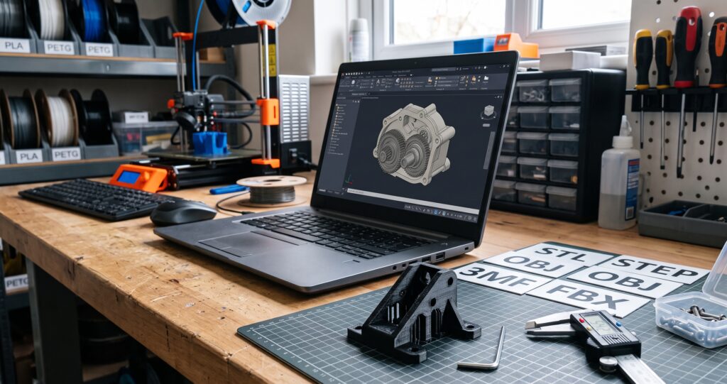
3D printing file formats • replacement-part quoting
You found the model. The download finished. There is even a file with “3D” in its description. But when you try to request a print, the next question is unexpected: Is this file actually ready to manufacture?
An STL, STEP, OBJ, 3MF, or FBX file can all describe some form of 3D data, but they do not preserve the same information or support the same workflow. The wrong handoff can hide the scale, flatten editable features into thousands of triangles, omit a texture file, combine several parts, or deliver an animated scene that still needs substantial preparation before a slicer can use it.
Quick answer: send the file closest to the work that still needs to happen
Send the native CAD file or STEP when a mechanical part may need dimensional edits. Send STL when the geometry is finished, correctly scaled, and ready for slicing. Send 3MF when the receiving workflow supports it and you need richer additive-manufacturing data or a clearly identified slicer project. Send OBJ for polygonal, sculpted, or textured geometry when the companion material and texture files are included. Treat FBX as a starting asset, not a printing promise: it often needs conversion, scale confirmation, part separation, mesh repair, and a manufacturing-permission check.
If you are unsure, do not convert the only copy and discard the original. Send the original file, a screenshot, one known dimension, and a description of the finished part. Kevin can evaluate what is usable before anyone rebuilds the wrong thing.
STL vs STEP vs OBJ vs 3MF vs FBX: what changes?
Think of the file extension as a clue about the model’s history and intended next step. It does not prove that the object is printable, accurate, complete, or licensed for manufacturing.
| Format | What it commonly carries | Strongest use in this workflow | What still needs checking |
|---|---|---|---|
| Native CAD .shapr, .f3d, and others |
Original bodies, and sometimes sketches, features, history, assemblies, or design intent | Revisions in the software that created the model | Software/version compatibility, linked components, missing references, and permission to share |
| STEP .step or .stp |
Standardized product-model and CAD geometry used across engineering and manufacturing systems | Editable mechanical geometry and cross-CAD handoff | Translation quality, bodies/components, units, and whether source design history is still needed |
| STL .stl |
A triangulated surface mesh | Finished single-geometry models that are ready to inspect and slice | Scale, resolution, holes, inverted faces, non-manifold edges, separate parts, wall thickness, and editability |
| 3MF .3mf |
A modern package designed for additive manufacturing; support can include units, objects, properties, color, materials, and extensions | Richer printable-model exchange or a complete slicer project when both sides use compatible software | Whether it is a model or slicer-specific project, software compatibility, embedded profiles, and machine-specific settings |
| OBJ .obj |
Polygonal geometry; color or texture workflows may rely on companion .mtl and image files | Organic models, sculptures, scan meshes, or visual assets | Missing companion files, scale, watertightness, intersecting shells, thin surfaces, and printable color separation |
| FBX .fbx |
Digital-content assets that may include geometry, scenes, materials, rigs, cameras, lights, or animation | Moving an asset between animation and content-creation tools | Which object is the printable part, pose, modifiers, scale, mesh integrity, wall thickness, part separation, conversion, and manufacturing rights |
| G-code .gcode and machine variants |
Sliced toolpaths and machine instructions | The specific printer, nozzle, material, and setup for which it was generated | Do not treat it as editable source geometry or send it for another machine unless specifically requested and reviewed |
The distinction between mesh and CAD geometry matters. Autodesk Fusion, for example, provides a dedicated process to convert a mesh body to a solid or surface body, and its guidance notes that repair and face-group preparation can improve the result. Conversion is a workflow—not proof that every triangle has recovered the original design intent.
Why STEP is often the best handoff for a mechanical replacement part
A replacement bracket, housing, knob, spacer, or cover usually has measurable interfaces: hole centers, shafts, clips, mating faces, fasteners, and clearances. If one of those dimensions changes, editable CAD geometry is usually more useful than a final triangle mesh.
STEP is formally tied to the ISO 10303 family. NIST describes STEP as a foundational standard used to share engineering and manufacturing data across organizations and supply chains. That makes STEP a sensible neutral handoff when the original native CAD format is unavailable or inconvenient.
When STL is enough—and when it creates extra work
STL remains a common, practical slicer input. Current Autodesk Fusion guidance exports STL and 3MF through a “Save As Mesh” workflow, while Shapr3D lists STL and 3MF among its 3D-print export options. For a finished model that opens at the correct size, forms a valid closed body, and needs no design changes, an STL can be completely appropriate.
The trouble begins when a mesh needs to become a new design. Moving a hole, thickening a wall, changing a fillet, separating a helmet into build-plate-sized pieces, or restoring a damaged cylindrical surface can be much more labor-intensive after the design has been reduced to polygon faces.
Before sending an STL, answer these five questions
- What is one dimension that proves the model’s intended scale?
- Is the file one finished object, an assembly, or several overlapping shells?
- Does the model need any dimensional change before printing?
- Are thin surfaces meant to be solid walls, or are they only visual skins?
- Do you own the design or have permission to manufacture it?
3MF can carry more—but identify what kind of 3MF you are sending
The 3MF Consortium describes 3MF as a format built to transfer full-fidelity models through additive-manufacturing workflows. Its current specification suite includes a core mesh specification and extensions for materials, properties, production information, and more.
That extra capability is useful, but “3MF” can describe different handoffs in everyday use. One file may be a model package. Another may be a slicer project containing arranged parts and printer, filament, or process settings. Prusa’s documentation, for example, explains that its slicer can save all models on a build plate and the slicer settings in one 3MF project.
OBJ and FBX may show the right shape without being ready to print
Useful for meshes and organic forms
OBJ can be a reasonable handoff for sculptures, scan-derived geometry, cosplay forms, and other polygonal models. If appearance depends on an .mtl file or image textures, include every companion file in one clearly named ZIP archive.
Built for digital-content exchange
Autodesk positions FBX as a 3D asset exchange format for animation and content-creation software. An FBX may contain printable geometry, but cameras, lights, rigging, animation, poses, modifiers, and scene scale do not automatically become a printable solid.
If your only file is FBX, keep it. Do not repeatedly convert and overwrite it. A useful evaluation starts by opening the original in compatible software, identifying the intended object and pose, applying the necessary transformations, exporting suitable mesh geometry, checking the scale, repairing the mesh, and deciding how the object should be split and oriented for the chosen manufacturing process.
A scan requires similar judgment. A scanner records visible surfaces; it does not automatically recover hidden geometry, ideal hole centers, thread specifications, snap-fit clearances, or the design decisions behind a worn part. See whether a compact scanner is useful for replacement parts before assuming a scan will replace measurement and CAD reconstruction.
Affiliate disclosure: Some links below may be affiliate links. If you buy through them, 3D Printing by Kevin may earn a commission at no extra cost to you. Recommendations are included only where they fit the reader’s project.
If scanning belongs in your workflow, you can compare 3DMakerpro scanning options. Treat the scan as measurement evidence and reference geometry—not as an automatic finished replacement part.
The seven-point file-readiness check
- Open the real file. A screenshot proves appearance, not geometry. Unzip the download and confirm which files are actually present.
- Confirm units and scale. Include one known dimension, such as overall width or hole spacing, even if the file appears correct.
- Identify every required part. Say whether the model is one piece, an assembly, a left/right pair, or a multi-color set.
- Inspect the body. Look for holes in the mesh, inverted faces, intersecting shells, zero-thickness surfaces, internal debris, and features thinner than the intended process can reproduce reliably.
- Mark the critical interfaces. A replacement part needs more than an overall size. Call out holes, shafts, clips, mating faces, fasteners, and movement clearances.
- Describe use and environment. Record load, heat, sun, moisture, impact, flexing, appearance, quantity, and the consequence of failure.
- Confirm manufacturing permission. Owning a downloaded file or game asset does not automatically grant the right to manufacture or sell it. Preserve the license or written authorization.
A file that passes these checks is still not automatically safe or suitable. It is simply a much better starting point for a realistic quote, process decision, and controlled test.
3D printing file-readiness planner
Choose the answers that match your project. The planner gives you a practical handoff checklist; it does not upload or save your selections.
Use the P.R.I.N.T. Method before you upload
P — Problem
Name what the finished part must solve. “Print this file” is an instruction; “replace the cracked enclosure latch” is the problem.
R — Requirements
List quantity, size, material demands, finish, color, deadline, budget, environment, and acceptable risk.
I — Interfaces
Mark every mating surface, hole, fastener, clip, shaft, cable path, clearance, and reference dimension.
N — Next-Best Materials & Methods
Choose the file conversion, modeling work, material, process, orientation, and inspection plan that fit the job.
T — Test & Tune
Print the smallest meaningful fit sample or first article, measure it, and revise before committing to the final quantity.
The file is only one input. A controlled replacement-part test fit reveals clearance and alignment problems that a screen cannot. Once the geometry is validated, material and connection choices still matter; see why more infill may not fix a layer-line break and why a screw hole can fail before the rest of the print.
If you are learning the whole workflow, P.R.I.N.T. It: Practical 3D Printing for Beginners connects file preparation, slicing, materials, calibration, troubleshooting, maintenance, and replacement-part thinking in one 40-page guide. For another established source of design and printer education, explore Maker’s Muse.
When it is time to validate the finished geometry, material consistency matters too. Explore COEX 3D filament and use code 3DPRINTINGBYKEVIN for 15% off. Select material from the part’s heat, load, weather, impact, flexibility, and testing needs—not from color alone.
Quick knowledge check
Choose one answer for each question, then check your score.
Frequently asked questions
Can Kevin print an FBX file?
An FBX can be evaluated, but it may not be ready to slice. The printable object must be identified, posed if necessary, converted to suitable geometry, scaled, checked for closed printable bodies, separated into practical parts, and reviewed for manufacturing permission. Conversion or remodeling time can affect feasibility and price.
Is an STL enough to request a quote?
Often, yes—especially when it is final, correctly scaled, complete, and needs no edits. Also include intended size, quantity, material or environment requirements, color, finish expectations, deadline, and intended use. If fit is critical, identify the mating dimensions.
Should I send STEP or STL for a replacement part?
Send both when possible. STEP is generally more useful for controlled CAD changes to mechanical geometry. STL documents the mesh you expected to slice. Include the native CAD source when the original design history or linked components may matter.
Can I upload a ZIP file?
A ZIP archive is useful when a project contains several parts, texture files, notes, or reference images, but the current intake form identifies STL, STEP, and OBJ as its direct model-file choices. Do not disguise a ZIP by changing its extension. Submit the project description first and ask Kevin to confirm the appropriate transfer method. A ZIP is only a container; the geometry inside still needs review.
What if I have no 3D file?
You may still be able to begin with the broken original, clear photographs, a dimensioned sketch, measurements, or a description of the problem. The first review determines whether modeling is practical and whether the project’s value supports the required design work.
Should I send G-code to a printing service?
Usually not unless the service specifically requests it. G-code is generated for a particular printer and process setup. Send the model or CAD source so the production provider can inspect, orient, support, and slice it for the actual machine, nozzle, material, and quality plan.
Fact-check references
- NIST: STEP at NIST
- 3MF Consortium: current 3MF specification suite
- Autodesk: FBX data-exchange overview
- Autodesk Fusion: convert mesh to solid or surface
- Shapr3D: supported export workflows
- Prusa Research: STL and 3MF project export guidance
Technical references and links reviewed August 19, 2026. Software support and file behavior can change; verify the current documentation for the exact software and version used in your workflow.
Have the file—but not a clear path to the finished part?
Send the original file, a screenshot, one known dimension, quantity, intended use, and any deadline that matters. Kevin will review whether the practical next step is direct slicing, file repair, CAD reconstruction, a test print, or a different manufacturing process.
Request a practical project review | See how discontinued-part replacement works
Your turn: Which file format has caused you the most confusion—STL, STEP, OBJ, 3MF, or FBX? Share what you were trying to make in the comments. Your example may help another reader recognize the missing step before they request a print.
