
A successful first day does not prove a long service life
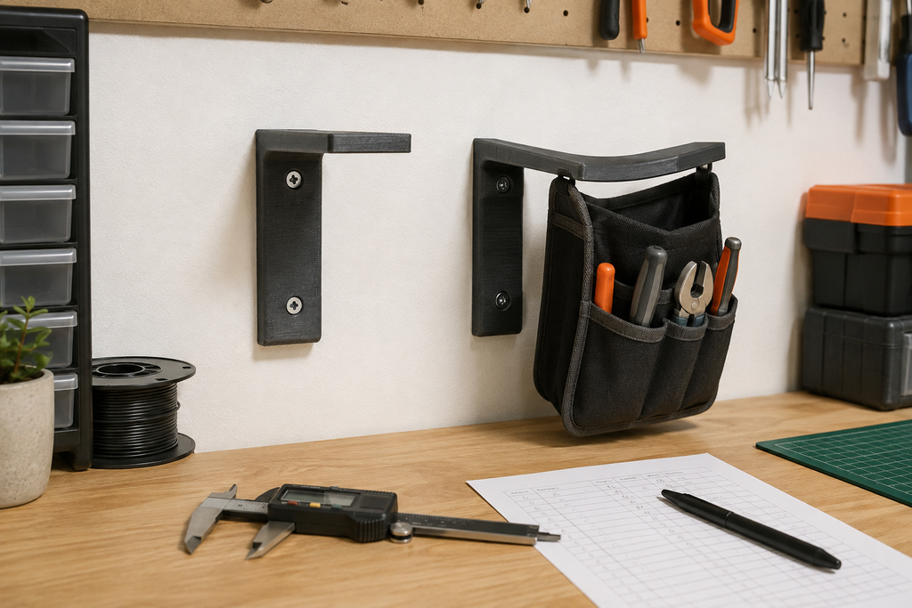
The bracket fit. The screws tightened. The shelf stayed level. Then, several weeks later, the printed arm had a visible droop—even though it never snapped and never felt hot enough to melt. That delayed movement is the problem makers describe as 3D print creep.
This is often creep: slow deformation while a thermoplastic remains under a steady load. The fix begins with the load path, not with a reflexive jump to 100% infill.
I have learned to separate two very different questions: Can the part carry the load right now? and Can the part hold its shape while carrying that load day after day?
A quick hand test answers only the first question. A printed hook, shelf bracket, clamp, camera mount, tool holder, or machine guide can feel reassuringly stiff during installation and still move slowly afterward. The load may be well below the force that would break the part in one pull.
Researchers have measured meaningful long-term creep in 3D-printed PLA even at temperatures below its glass-transition region. Other experiments show that build direction and raster orientation change creep behavior because FDM parts are not mechanically identical in every direction. That is why a spool’s tensile-strength number cannot predict the service life of your particular print by itself.
3D print creep is not the same as ordinary print warping
“Warping” usually describes a part lifting or changing shape while it is being printed and cooling. Creep happens after the part is finished, often while it looks completely normal. A load remains in place, the material slowly strains, and the geometry drifts.
The distinction matters because a brim, cleaner build plate, or warmer enclosure may fix printing-stage warping but will not rescue a finished bracket with an inefficient load path. If your trouble begins on the bed, use the guide to stopping PLA, PETG, and ABS warping. If it begins days or weeks after installation, continue here.
| What you observe | Likely failure mode | Useful first check |
|---|---|---|
| The part droops a little more each day under a steady load | Creep | Load, temperature, lever length, section thickness, and material |
| The part bends under load but returns when unloaded | Elastic deflection | Stiffness and geometry; watch whether recovery becomes incomplete |
| The part changes shape after one hot afternoon | Thermal softening or heat-assisted creep | Actual service temperature and the exact filament data sheet |
| A small crack grows after repeated use | Fatigue or a stress concentration | Cycles, sharp corners, holes, layer direction, and flex range |
| The part separates cleanly along printed layers | Layer-bond failure | Orientation, extrusion, cooling, speed, moisture, and section design |
A real part can experience more than one mode. A warm clip may creep open, then crack after repeated flexing. A bracket can sag until a screw begins pulling against one edge of its hole. Diagnosis should follow the visible evidence instead of forcing every delayed failure into one label.
Why a “strong” filament can still sag
Strength is not one property. Tensile strength measures a material under a particular test. Stiffness describes how much it deflects under load. Toughness relates to how it absorbs energy before fracturing. Creep resistance addresses time-dependent movement.
A rigid PLA part may perform impressively in a quick bend test while being a poor choice for steady load near a warm window, inside a vehicle, or beside heat-producing equipment. PETG often brings useful toughness and temperature resistance, yet it can still creep when continuous force and warmth combine. ABS or ASA may provide more temperature margin, but they bring their own print-control and ventilation requirements. Engineering materials are not automatic answers either; the printer, drying, orientation, geometry, and validation process still matter.
For a broader breakdown of stiffness, toughness, heat, impact, and orientation, read how to choose filament for load-bearing 3D-printed parts. If the part will live in a vehicle, the focused comparison of PLA, PETG, and ABS in a hot car is the better next step.
The geometry often matters more than the extra infill
Imagine a wall-mounted hook. The weight hangs at the end of a long horizontal arm. That distance creates leverage at the wall connection. Filling the interior with more plastic may help, but it does not remove the inefficient load path.
A deeper vertical section, shorter arm, triangular gusset, curved transition, wider mounting face, or second support can produce a much larger improvement than hiding more material in the center. The right change depends on where the part bends and how the force reaches the mount.
Long, thin cantilever
- Load sits far from the mount
- Sharp inside corner concentrates stress
- Thin section allows visible deflection
- More infill leaves the basic lever unchanged
Shorter, supported path
- Load moves closer to the mount
- Gusset or rib carries force into the base
- Generous radius softens the transition
- Walls follow the part’s main stresses
Start with these six design questions
- Can the load move closer to the support? A shorter lever reduces the bending demand without changing filament.
- Can the part become deeper in the bending direction? Strategic section depth often improves stiffness more efficiently than uniform thickness.
- Can a gusset, rib, arch, or second contact point redirect the load? Support should connect the loaded feature to the mounting region rather than float cosmetically nearby.
- Are sharp corners starting the problem? A suitable radius can reduce stress concentration, but it must leave enough room for the mating assembly.
- Is a screw or insert crushing a small area? Spread clamp force with adequate material, a washer, a boss, or a better interface where appropriate.
- Does the part need to be one printed piece? A metal fastener, pin, rod, washer, or purchased bracket may carry the sustained load better while the printed part handles alignment or enclosure duties.
Then compare walls and infill deliberately. Walls frequently place material where bending stresses are highest, while infill supports the interior and top surfaces. The correct balance depends on geometry and load direction. The site’s infill-density guide explains how to run a three-slice comparison instead of treating 100% infill as a universal strength setting.
Print orientation changes the long-term result
FDM parts are anisotropic: they do not behave the same way in every direction. Extruded roads can be strong along their length while the bonds between layers become a separate design concern. Research on printed PLA creep has found that build and raster orientations change time-dependent behavior.
Orientation also changes the shape and continuity of perimeters around holes, ribs, hooks, and thin sections. Turning the part 90 degrees can improve one load path while making another interface weaker or rougher. There is no universally “strongest side” without knowing how the finished part is loaded.
If fasteners are part of the failure, also check why 3D prints crack around screws. Tightening a screw until the part “feels solid” can preload the plastic continuously and create the same time-plus-load problem before the bracket carries anything else.
A practical seven-step fix for a sagging part
- Unload the part and document it. Photograph the installed position, measure the deflection, record the load, and note the time and temperature conditions. Do not keep using a visibly changing part where failure could hurt someone or damage equipment.
- Find the first moving region. Look for whitening, oval holes, crushed washer marks, a bowed arm, an opening clip, lifted screw heads, or a concentrated bend near an inside corner.
- Separate material movement from loose hardware. Check the mating surface, fasteners, anchors, inserts, and mounting face. A loose wall anchor is not polymer creep, although both can occur together.
- Reduce the demand. Shorten the lever, lower the load, add a support, widen the mount, or split the job between printed and conventional hardware.
- Rebuild the stressed region. Add section depth, useful walls, radii, ribs, gussets, bosses, or load-spreading features where the evidence points—not everywhere.
- Choose the final material and orientation together. Match temperature, load duration, moisture, sunlight, impact, printer capability, and safety requirements. Use the exact filament maker’s data sheet as a starting point.
- Run a time-based test. Measure the finished part at installation, after initial loading, after 24 hours, and again after several days or weeks as appropriate. One successful hour is not a life test.
How to test a redesign without pretending it is certified
A useful shop test reproduces the real direction of force, attachment method, representative load, and expected environment as closely as practical. It also creates measurements you can compare.
Set a baseline
Measure a reference distance or angle before loading. Mark the points so every later measurement uses the same locations.
Apply the real load path
Mount the part as it will be used. A bench test that supports the arm differently may hide the weakness you need to see.
Measure over time
Record immediate deflection, recovery after unloading, and permanent change at planned intervals. Photograph the same view each time.
When practical, print more than one final specimen. One sample cannot reveal normal variation in extrusion, filament condition, layer bonding, or dimensions. If the part is intended for production, a controlled test fit should be followed by validation in the final material and configuration before multiple copies are made.
Desktop FDM parts should not be treated as automatic replacements for load-bearing safety hardware, guards, lifting equipment, seat or restraint components, pressure parts, medical devices, critical electrical parts, or structures whose failure could cause injury. A better material does not remove the need for appropriate engineering and validation.
The sustained-load part planner
Fill this in before changing the slicer. It is designed to separate the real requirement from the first fix that comes to mind.
Use the P.R.I.N.T. Method™ for long-term performance
Describe what bent and what the part must still accomplish.
Record load, duration, heat, exposure, lifespan, and failure consequence.
Map mounts, screws, clips, contact faces, clearances, and force entry points.
Choose geometry, material, orientation, hardware, and process as one system.
Measure under representative load, revise one defined weakness, and retest.
The complete P.R.I.N.T. workflow is included in The Practical Guide to 3D Printing: 2026 Expanded Edition, along with setup, slicing, calibration, materials, troubleshooting, replacement-part planning, and maintenance guidance.
A material purchase should follow the redesign
A dependable filament helps you reproduce the test and final part consistently, but a premium spool cannot correct a poor load path. Prove the geometry, identify the environment, and confirm that your printer can process the chosen material safely before buying.
Affiliate disclosure: The following material link is a partner link. If you purchase through it, I may earn a commission at no additional cost to you. I include it because consistent filament is relevant to controlled testing—not because one brand or polymer can guarantee a load-bearing result.
For PLA, PETG, ABS, ASA, and flexible-filament options, you can compare COEX filament. Use code 3DPRINTINGBYKEVIN for 15% off when the offer is available. Confirm the current technical data, printer requirements, and safety guidance for the exact product you select.
Four-question knowledge check
Select one answer for each question, then check your score.
Frequently asked questions
Can PLA creep at room temperature?
Yes. Published research has observed long-term creep in printed PLA below its glass-transition region. The amount and rate depend on the material, load, geometry, orientation, temperature, processing, and time. Room temperature is not an automatic guarantee of dimensional stability.
Is PETG better than PLA for parts under constant load?
Not universally. PETG often offers useful toughness and more temperature resistance than standard PLA, but it can still creep. A stiff, cool, lightly loaded PLA fixture may outperform a thin, warm PETG hook with long leverage. Compare the exact filament data, redesign the load path, and test the final configuration.
Will 100% infill stop a 3D print from bending?
It may increase stiffness or strength in some geometries, but it is not a guaranteed cure. Shortening the lever, increasing section depth, adding a real gusset, improving walls and orientation, or sharing the load with conventional hardware can be more effective and use less material.
How long should I load-test a 3D-printed bracket?
There is no universal duration. The test window should reflect the intended service life and risk. Record immediate deflection and continue at planned intervals such as 24 hours, several days, and longer when appropriate. Higher-consequence applications require qualified design and testing rather than a casual shop trial.
Can annealing prevent PLA creep?
Some PLA formulations can gain heat resistance through a controlled annealing process, but dimensions can shrink, expand, or warp. Annealing does not correct excessive load or leverage. Follow the exact filament maker’s procedure and validate the final dimensions and performance.
Should I reprint a sagging part in ABS or ASA?
Only after reviewing the job. ABS or ASA may provide more thermal margin than standard PLA, yet the part can still fail if its geometry, orientation, fasteners, load, or process is unsuitable. These materials also need controlled printing and appropriate ventilation.
When should I stop testing and use another manufacturing method?
Use another route when the required load, heat, precision, lifespan, certification, or failure consequence exceeds what you can responsibly validate with the available material and process. Metal hardware, machining, molding, or professional engineering may be the practical answer.
Sources and further reading
- Journal of the Mechanical Behavior of Biomedical Materials: build direction, raster orientation, and creep response of FDM PLA
- Polymers: tensile creep behavior of PLA 3D-printed parts
- Fischbach and Weinberg: long-term flexural creep in 3D-printed PLA
- Prusa Research: filament material guide
- CDC/NIOSH: Approaches to Safe 3D Printing
The practical takeaway
If a part shows 3D print creep, do not begin by making the same model solid. Document the failure, map the load, shorten the leverage, strengthen the working section, reconsider orientation and material, then measure the final design under representative load. A part is not proven when it leaves the build plate. It is proven by what it continues to do.
