
Functional 3D printing · Design for the second opening
The cover clicks into place. The fit looks right. Then you open it to adjust something—and a little plastic tab stays behind.
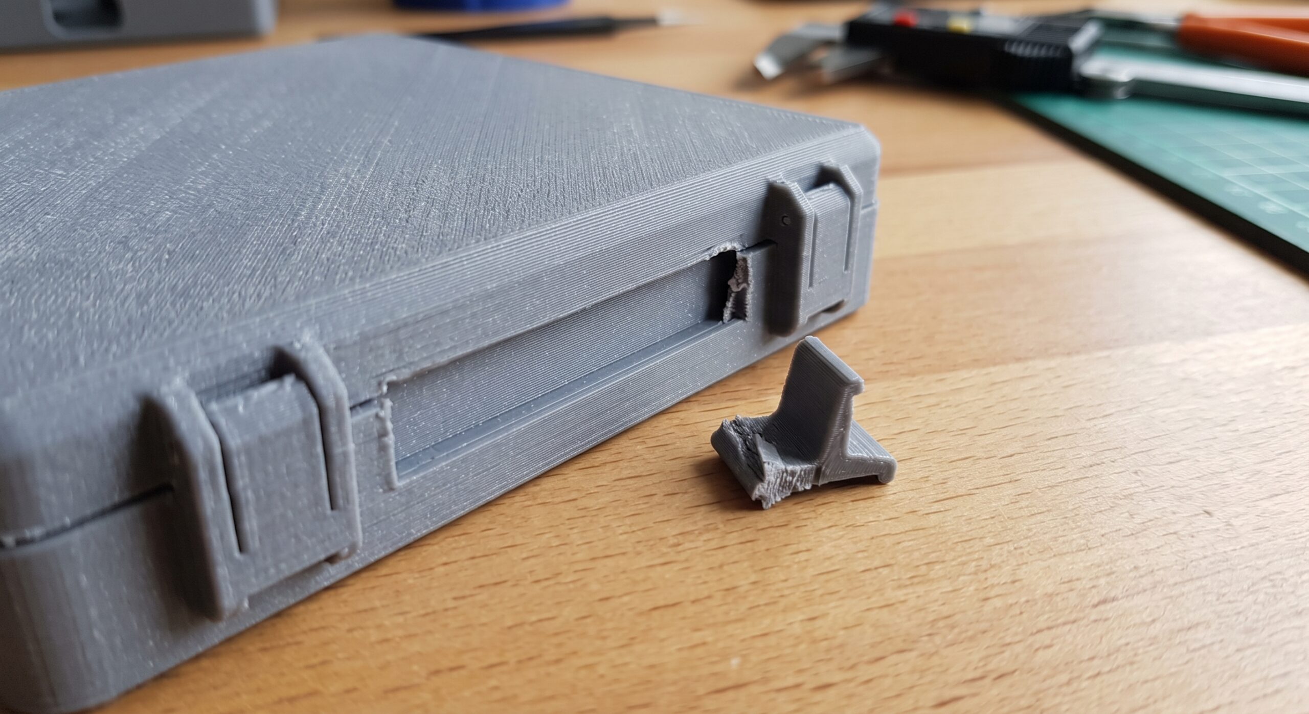
If your 3D-printed clip breaks when you remove it, the next useful question is not simply which filament is stronger. Ask what the clip must do to get back out. A snap-fit needs a workable exit as well as a workable entrance.
Quick answer: Why does a 3D-printed clip break?
A clip can fail because it bends too far, concentrates stress at its root, separates along print layers, or has a retaining face that cannot release with the available movement. Repeated flexing can also cause fatigue. The timing of the failure helps you choose what to investigate. [1] [2] [3]
Start with the release path. Check whether you can reach and deflect the tab after assembly. Then test a small version containing the complete clip, its root, and the mating ledge before reprinting the whole housing.
Disclosure: This article includes a COEX affiliate link. A purchase through it may earn Kevin a commission at no additional cost to you. The ebook below is Kevin’s own paid resource. Read the affiliate disclosure.
First, separate a fit problem from a release problem
Keep the broken piece and look at where it separated. Write down whether the failure happened while closing, opening, or simply sitting assembled. Do this before changing the model: it gives the next version a specific problem to solve.
| What happened? | Check first | Useful next action |
|---|---|---|
| Breaks on first assembly | Required bending travel, interference, root, print quality. | Watch where the hook contacts the mating edge. Stop forcing the fit. |
| Closes, then breaks on removal | Retaining face and access to the release tab. | Work out how the hook clears the ledge before pulling again. |
| Works several times, then cracks | Repeated flexing, earlier damage, wear, or changing technique. | Record cycles and inspect the same locations after each checkpoint. |
| Splits along a layer boundary | Orientation and bonding at the bending region. | Compare the failure with the slicer’s layer direction. |
| Loses grip while left assembled | Whether the arm stays bent or the mating parts move. | Record time under load separately from opening cycles. |
Repeated-use fatigue and a one-time overload are different mechanisms. A crack after several openings does not, by itself, prove fatigue. Likewise, a tab that slowly loses its hold without being opened needs a sustained-load investigation, not just a cycle count. Snap-fit design references identify both fatigue and time-dependent loss of performance as concerns. [1] [3]
If the surrounding housing will not seat even with the clip held clear, start with a separate test of the replacement part’s fit. The tab may be taking the blame for a separate dimensional problem.
Decide how often this connection must open
A permanent snap and a serviceable snap are different design choices. A hook can slide over an entry ramp and catch behind a much steeper face. That shape may retain the part well while offering no easy way to pull it apart. The undercut and release geometry determine whether a joint is separable. [2] [4]
Write a plain-language requirement: “Open this cover by hand to replace a battery,” or “Assemble this once and leave it closed.” Include who will open it and whether the intended release area remains reachable in the installed position.
| Your requirement | Candidate approach | What to demonstrate |
|---|---|---|
| One assembly, no planned service | A retaining snap designed for that purpose. | Assembly without damage and adequate retention. |
| Occasional access | A snap with a reachable release tab or window. | Controlled removal with the surrounding parts installed. |
| Frequent opening | A deliberately reusable latch, or a screw-fastened cover. | Repeated operation and the required holding function. |
| Defined clamping or adjustment | A fastener arrangement selected for the load. | The required clamp behavior and service procedure. |
This table is a selection aid, not a strength ranking. If a removable screw connection better suits the job, plan the attachment with the guide to screws stripping in 3D-printed parts.
Infographic 1 · Follow the whole motion
One clip. Three separate jobs.
The lead-in moves the hook past the mating ledge.
The hook seats and provides the intended retention.
An accessible movement clears the hook before separation.
For a reusable connection, check all three with the cover installed.
Change the bending motion before adding bulk
Give the tab somewhere to go
With the parts apart, point to the hook, the ledge it catches, and the space the arm moves into. Next, imagine the cover closed. Can a finger or the intended tool still reach the release? Can the hook move far enough to clear the ledge without hitting another wall?
For a strongly retaining face, a release window may be more useful than harder pulling. Fictiv’s design guide discusses the relationship between the return angle and disassembly, including access windows for otherwise difficult-to-release hooks. [2]
Make the release action understandable to the next person. “Press here, then lift” is a better design target than hoping everyone discovers a hidden twisting motion.
Look closely at the root
The root is where the flexible arm joins the body. A sharp internal corner concentrates stress. A suitable fillet and a thoughtfully tapered arm can improve the distribution of strain; neither replaces checking the actual printed geometry. Bayer’s guide explains these principles for plastic snap joints. Its molded-material dimensions and allowable strains should not be treated as validated FDM settings. [4]
Thicker is not an automatic fix
For a simple cantilever required to move the same distance, increasing bending thickness raises the surface strain; increasing arm length reduces it. That is why making a short tab chunkier can make a forced fit harder to survive. Real housings, tapered arms, and flexible mating parts change the calculation. [2]
Try a clearly identified revision: more usable arm length, less required hook travel, or an improved root transition. Keep the other dimensions stable so you can tell which change helped. Do not reduce engagement until the cover merely falls off; retention remains part of the requirement.
Infographic 2 · Geometry tradeoffs
Follow the required travel
Can reduce bending strain for the same tip movement.
Can increase strain when the required movement stays the same.
Can reduce required movement—but still check retention.
Qualitative guidance for a simple cantilever. No universal clip dimensions or load rating are implied.
Check print direction and the surfaces that actually touch
A clip is not just its CAD outline. The layer direction passes through its root and bending arm. Protolabs Network recommends considering orientation so a cantilever is not built in a vulnerable vertical arrangement. Examine where bending would tend to open the layer interfaces, and test the orientation planned for the final part. [1]
If you already see separation between layers, use the layer-line failure guide alongside this one. Increasing infill alone does not establish that the clip’s weakest region has been fixed.
Look at the ledge and hook after support removal, too. Record visible ridges, scars, and any sanding in your test notes. The guide to support scars and bad fit helps separate a finishing issue from the clearance you intended in CAD.
Use the same finishing procedure for each comparison. If one sample is heavily sanded and another is untouched, you are comparing more than the model revision.
Choose a material candidate, then test that exact print
PLA can be useful for checking shape and assembly, but a PLA fit prototype does not establish a reusable clip’s life. Prusa describes PLA as comparatively brittle and limited in heat resistance. [6]
PETG is a reasonable candidate for some functional clips because it combines toughness with some flexibility. Prusa’s material guide describes those properties, but they do not guarantee that any particular PETG tab will survive its required motion. [5]
Record the manufacturer, product, and print profile—not just “PETG.” Keep the material constant while comparing geometry; then compare a material change using the same design and intended environment. Avoid changing orientation, dimensions, and filament at once.
Buying material? You can browse COEX filament through Kevin’s affiliate link. Check the chosen product’s guidance against your printer and application. A purchase is optional; a useful release-path test may teach you more than another spool.
Print a paired test piece before the whole enclosure
Use a small test coupon containing the complete arm, root transition, hook, mating ledge, and enough surrounding wall to represent their support. An isolated flexible strip cannot tell you how the actual catch releases.
Keep the final orientation and relevant slicer settings. A coupon with a much stiffer or thinner base than the housing may behave differently, so treat it as screening. Confirm the promising revision in the complete assembly. This follows the same practical sequence as testing a replacement part’s fit.
- Define one cycle. Assemble fully, use the intended release, and separate the parts. Keep the motion consistent.
- Set acceptance conditions first. For example: the cover seats, the tab returns, the release is reachable, and the cover stays closed during its intended handling.
- Record the first cycle. Photograph the root and hook before and after. Note any need for unexpected force or twisting.
- Repeat and inspect. For a low-consequence bench comparison, checkpoints after 1, 5, and 10 cycles can reveal early problems. These are suggested observation points, not a durability standard.
- Stop a damaged sample. Investigate a crack, new whitening, permanent bend, or loss of retention. Whitening is a warning to inspect, not proof of a specific failure mechanism.
- Compare more than one copy. Label the revision and test another sample. Then test the complete assembly against the real opening frequency, surroundings, and holding requirement.
Passing ten openings means only that the sample passed those ten openings under those conditions. It does not establish hundreds of cycles, outdoor life, or a safe load rating. Repeated flexing and environmental conditions both matter to snap-fit performance. [3]
Infographic 3 · Repeat the same check
Assemble → seat → release → inspect
Does the intended motion bring the parts together?
Does the hook engage and the cover stay in position?
Can you clear the hook without an improvised struggle?
Compare the root, hook, return position, and retention.
Record the revision, material, orientation, cycle count, and observations together.
Once a revision works, use the repeat-print consistency guide to investigate differences between copies before committing to a batch.
Put the clip into your P.R.I.N.T. planner
Copy these five prompts into your project notes before the next revision. Keep the answers with the model and print profile.
Problem
What fails: closing, holding, or reopening? Where is the damage?
Requirements
How often must it open? Who operates it? What holding behavior and environment must it tolerate?
Interfaces
Identify the hook, mating ledge, root, bending space, and release access after installation.
Next-Best Materials & Methods
Choose one geometry revision and a material candidate. Would a different closure serve the job better?
Test & Tune
Set acceptance conditions. Record the paired coupon, cycles, observations, and final assembly check.
These checkboxes are a temporary on-page checklist; copy your results into your planner before leaving.
Build a more useful project record
For Kevin’s wider planning approach, see The Practical Guide to 3D Printing: 2026 Expanded Edition. Use the P.R.I.N.T. prompts above to turn this failed clip into a focused next test.
Four-question knowledge check
Select one answer per question to reveal feedback. You can change an answer or reset the check. Nothing is submitted.
Frequently asked questions
Why does my clip fit once but break when I open it?
The entry ramp may permit assembly while the retaining face resists removal. Check the release path and bending travel. A first-opening failure is not enough evidence to call it fatigue. See sources 2 and 3.
Should I make the arm thicker?
Not automatically. For a simple cantilever with the same required tip travel, extra bending thickness increases surface strain. Review usable length, root geometry, and interference before choosing a revision. See source 2.
Is PETG always better than PLA for clips?
No material name guarantees a successful connection. PETG is a useful candidate where toughness and flexibility help, but geometry, print quality, environment, and required service still need testing. See sources 5 and 6.
What clearance should I use?
There is no universal clearance for every printer, material, and snap geometry. Separate the sliding clearance from the hook’s retaining engagement, then compare labeled test pairs. See source 1.
How many cycles should a reusable clip survive?
Start with the actual service requirement and consequences of failure. The ten-cycle example above is only an early screening exercise. A long-life claim needs evidence appropriate to that claim.
Can I use the same coupon for every housing?
Use it to compare revisions, but confirm the full assembly. Surrounding wall support and access can change when the connection moves into the finished enclosure.
What happened when you opened yours?
A functional-printing community example celebrates a snug first test that also comes apart; the comments raise the practical question of reaching the release. That is useful inspiration, not a measured service-life result.
Tell us in the comments: What does your clip hold, which material did you print, and did it fail while closing, opening, or after several uses? Could you reach the release once it was installed?
If you tried a revision, share the one thing you changed and what happened next. Those details make the conversation more useful than simply naming a “stronger” filament.
Need help defining a functional part? Start a project inquiry with photos, mating-part details, and the opening requirement.
Sources and further reading
- Protolabs Network: designing snap-fit joints for 3D printing — orientation, tolerances, and failure considerations.
- Fictiv: how to design snap-fit components — cantilever behavior and release geometry.
- Xometry: snap-fit joint design — repeated flexing, environment, and connection choices.
- Bayer MaterialScience: Snap-Fit Joints for Plastics (PDF, hosted by MIT) — general mechanics; molded-material data are not FDM validation.
- Prusa: PETG material guide.
- Prusa: PLA material guide.
