
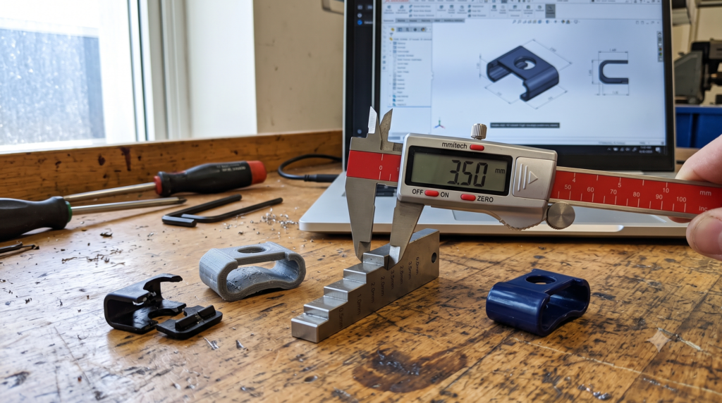
A hole can print smaller than expected. A peg can grow just enough to bind. A clip can lose flexibility because of its orientation. A replacement cover can match the broken outline yet collide with a screw, radius, or hidden surface. Before printing the entire part again, isolate the interface and test only the few millimeters that control the fit.
Why does a 3D-printed part not fit even when the CAD dimensions are correct?
The printed result is affected by nozzle width, layer height, material shrinkage, first-layer expansion, hole orientation, cooling, extrusion calibration, support contact, printer accuracy, and the clearance designed between mating surfaces. CAD describes the intended geometry; it does not guarantee that every printer and material will reproduce that geometry exactly. The quickest fix is usually a small interface test—not scaling the entire model blindly.
Accuracy and fit are related, but they are not the same thing
A printer can reproduce a part consistently while still producing a hole slightly smaller than the CAD model. That machine may be repeatable, but the design still needs enough clearance for the intended fit.
A sliding lid, press-fit pin, rotating hinge, snap clip, and bolt hole do not need the same amount of space. “Perfectly accurate” is not a useful fit specification by itself. The real requirement is whether the two surfaces assemble, move, hold, or release as intended.
3D Printing by Kevin principle: Test the interface that controls the function before spending hours printing everything around it.
Use the P.R.I.N.T. Method™ to diagnose the fit
The goal is not to guess a new scale percentage. It is to identify the dimension and process condition responsible for the mismatch.
Problem
Define whether the part is too tight, loose, shifted, warped, or blocked.
Requirements
Decide whether the fit should slide, rotate, snap, press, or remain fixed.
Interfaces
Identify the exact hole, peg, slot, lip, clip, shaft, or mating face involved.
Next-Best
Choose a local clearance change, orientation change, test coupon, or process adjustment.
Test & Tune
Print the smallest useful sample, measure it, and revise only what the result supports.
What kind of fit are you trying to create?
| Fit | What it should do | Common failure | Best first test |
|---|---|---|---|
| Sliding fit | Move freely without obvious wobble | Layer texture or undersized opening causes binding | Short rail-and-slot sample |
| Press fit | Hold through controlled interference | Part cracks, deforms, or will not start | Small pin-and-hole ladder |
| Snap fit | Flex during assembly and engage a catch | Clip is too stiff, weak across layers, or misses the catch | One clip and mating lip |
| Rotating fit | Turn without separating or grinding | Fused surfaces, rough holes, or excessive looseness | Short hinge or shaft sample |
| Fastener clearance | Allow a screw or bolt to pass or engage properly | Hole prints undersized or misaligned | Thin hole-size gauge |
Six reasons the finished part may not match the model
Holes print differently from outside walls
Internal curves can become undersized because of extrusion width, polygonal geometry, cooling, and the direction in which the hole is printed.
The first layer spreads
Excessive first-layer compression can create an elephant-foot edge that blocks a slot or prevents a part from seating fully.
The material changes as it cools
PLA, PETG, ASA, and other materials do not shrink, flex, or retain dimensions in exactly the same way.
Orientation changes the result
A horizontal hole, vertical hole, upright clip, and flat clip can have different surfaces, support marks, strength, and dimensional behavior.
The measurement missed an interface
A fillet, chamfer, screw head, tapered wall, hidden stop, or damaged fragment may control the fit even when the main dimensions are correct.
The design has no working clearance
Two CAD surfaces that touch perfectly leave no room for extrusion variation, texture, debris, movement, or assembly.
Do not scale the whole part to fix one bad hole
Increasing the entire model by one percent may enlarge the hole, but it also changes every mounting point, outer wall, clip position, screw spacing, and mating surface. The original problem can disappear while three new ones appear.
Better correction: Adjust the local feature that controls the fit. Enlarge the hole, offset the mating face, shorten the peg, modify the clip, add a chamfer, or compensate for the first layer where the evidence points.
The small test that can prevent a full reprint
Copy only the critical interface into a separate test model. Keep enough surrounding geometry to reproduce the real orientation and wall behavior, but remove everything that does not affect the fit.
- Isolate the hole, peg, clip, slot, rail, hinge, or mating lip.
- Print the sample in the same orientation as the final part.
- Use the same material, nozzle, layer height, walls, and profile.
- Create several controlled clearance options when practical.
- Label each option directly in the model or immediately after printing.
- Let the sample cool before measuring or testing.
- Check assembly, movement, retention, and removal—not size alone.
- Apply the winning dimension to the final model.
This follows the same workshop logic described in The Most Underrated 3D-Printed Tool in My Workshop : a small gauge can provide more useful information than another full-size failure.
What does the failed fit tell you?
Choose the description closest to the actual result before changing the model.
Inspect tapers, bottom corners, first-layer expansion, depth, and hidden stops.
Check the opening size, entry chamfer, orientation, support marks, and local clearance.
Reduce the local gap, improve alignment, or add a controlled retention feature.
Measure the printed result—not only the original object
The original part tells you what the replacement must fit. The test print tells you what your printer, material, orientation, and profile actually produced.
Compare the CAD dimension, printed dimension, and mating object. That three-way comparison reveals whether the correction belongs in the model, slicer, printer calibration, or measurement process.
Begin with How to Measure a Part for 3D Printing when recreating a missing or broken component.
When sanding or drilling is reasonable—and when redesign is better
Light finishing may be practical
Removing a support mark, cleaning a small hole, trimming a minor burr, or easing an entry edge may be appropriate for a one-off part.
Repeated correction belongs in CAD
If every copy needs the same drilling, filing, or sanding, update the model or manufacturing process before producing a batch.
Do not force a stressed assembly
Driving a brittle part into place can create hidden cracks, damaged equipment, distorted holes, or a failure that appears later.
Helpful resources for the next step
Need a replacement part?
Read Discontinued Plastic Parts Replaced with 3D Printing for the complete evaluation and recreation process.
Can the weak area be improved?
Explore From Broken Part to Better Design for a function-first redesign workflow.
Want the complete planning system?
Continue with P.R.I.N.T. It: Practical 3D Printing for Beginners for materials, setup, troubleshooting, replacement parts, and testing.
Readers building their own projects can also review whether faster printing improves functional results before rushing fit-check samples through an unverified speed profile.
Quick knowledge check
Open each question to test the fit-troubleshooting process.
1. Why can correct CAD dimensions still produce a poor fit?
The final dimensions are influenced by the printer, extrusion, material, cooling, orientation, first layer, supports, and the clearance designed between mating surfaces.
2. Why is scaling the entire part usually a poor first fix?
Scaling changes every dimension. It may repair one hole while moving mounting points, outer walls, screw spacing, and other features that were already correct.
3. What should remain consistent during a fit test?
Use the same material, orientation, nozzle, layer height, wall settings, and relevant print conditions planned for the final part.
4. When should the CAD model be revised instead of hand-finishing each part?
Revise the design when the same correction is required repeatedly, when quantity increases, or when manual finishing creates inconsistent dimensions.
Frequently asked questions
How much clearance should I add between 3D-printed parts?
There is no universal value. The correct clearance depends on the printer, material, orientation, layer height, feature size, intended movement, and whether the fit should slide, rotate, snap, or press. A small clearance ladder is more dependable than copying one generic number.
Why do 3D-printed holes come out too small?
Internal curves can be affected by extrusion width, faceted model geometry, cooling, orientation, first-layer compression, and printer calibration. Test the hole in its final orientation before changing the full model.
Should I calibrate flow before changing the CAD file?
Check for broad extrusion problems when many unrelated parts print oversized or undersized. When one local interface fails and the rest of the part is correct, a local design adjustment may be more appropriate.
Can I drill a 3D-printed hole to final size?
Often, yes, for suitable non-critical parts. Support the component, use appropriate tools and speeds, and avoid excessive heat or force. Redesign the hole when repeated production requires the same correction.
Why did the prototype fit in PLA but the PETG version does not?
Materials differ in shrinkage, flexibility, extrusion behavior, temperature, cooling, and surface texture. A final-material fit test is more reliable than assuming the PLA prototype transfers perfectly.
Can a custom replacement fit correctly on the first print?
Sometimes, especially when the original and interfaces are accessible. A prototype is still normal engineering practice when geometry is damaged, measurements are incomplete, tolerances are tight, or the consequences of a poor fit are significant.
Do not reprint six hours of plastic to test six millimeters of fit.
Send clear photographs, measurements, broken fragments, available files, and an explanation of how the part connects. The project review can identify the critical interface, choose a practical test, and reduce the risk of another full-size failure.
Achievable dimensions and clearances vary with printer condition, material, geometry, orientation, nozzle, layer height, slicer settings, cooling, supports, measurement method, and intended use. Test functional interfaces before relying on a printed component where poor fit or failure could cause injury or equipment damage. [1]: “Functional 3D Prints That Save $500 a Month”. [1]: https://3dprintingbykevin.com/stop-printing-benchys-functional-3d-prints-that-save-500-a-month/ [2]: “Understanding 3D Printing Tolerances”
Understanding 3D Printing Tolerances: A Guide to Achieving Precision in Additive Manufacturing
