
The support peeled away. Nothing snapped. The print looks finished—until the bracket rocks, the cover refuses to seat, or the mating face leaves a visible gap.
Clean removal only tells you that the support separated. It does not prove that the surface above it printed flat, at the intended height, or smooth enough to function as an interface.
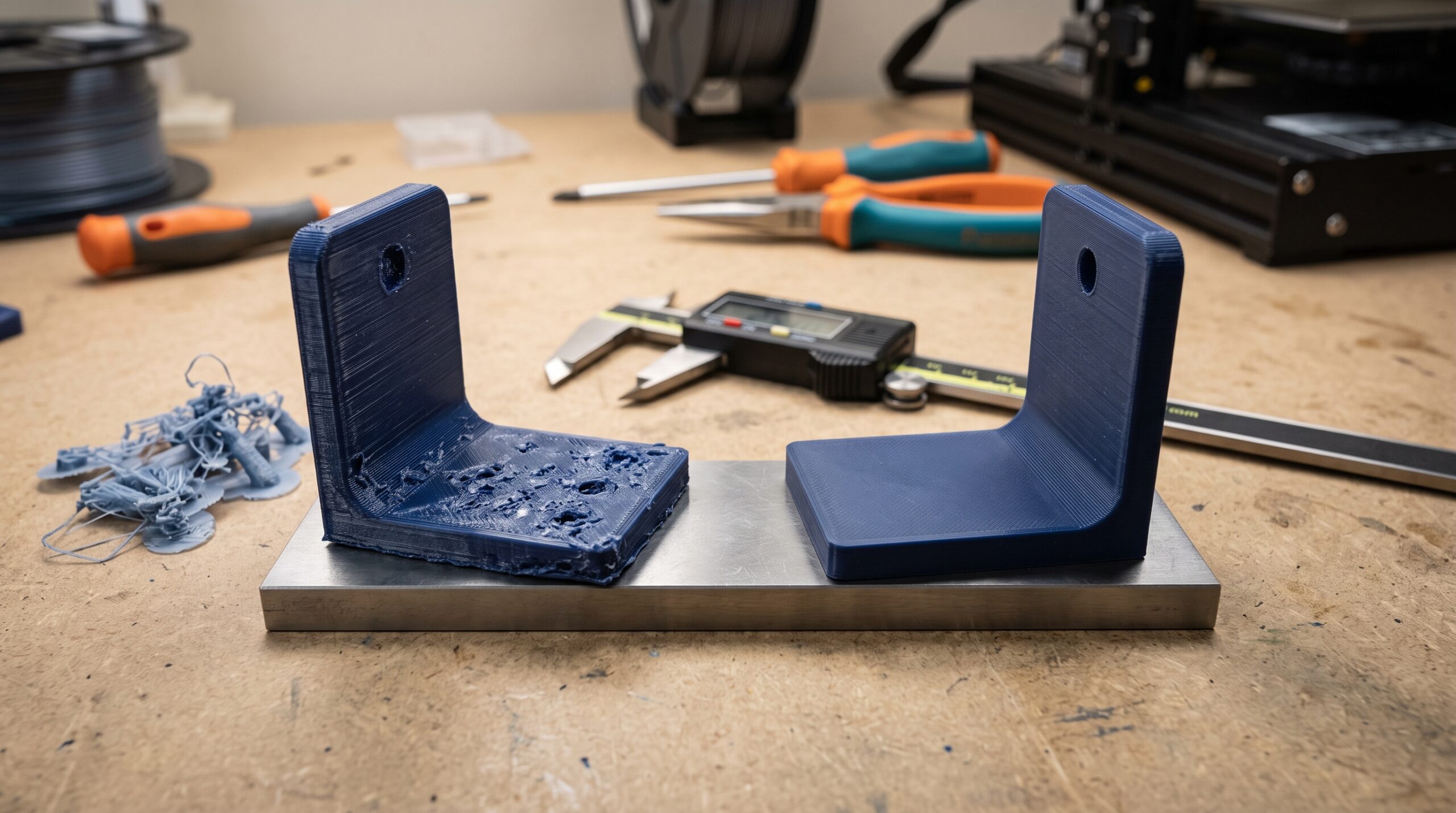
If a 3D-printed part fits everywhere except the supported surface, do not scale the entire model. First confirm that support texture, sag, residue, or Z-gap error is blocking the fit. Then protect the critical face through orientation or geometry when possible. If support is unavoidable, tune one variable at a time—usually contact distance, interface layers, pattern spacing, speed, or cooling—and print a small section before repeating the full part.
A supported underside is not printed like a normal top or bottom surface. With same-material supports, the slicer usually leaves a deliberate separation so the temporary structure can be removed. The first model layer above that gap must bridge across the support interface instead of being pressed neatly against a solid build surface.
That compromise is useful, but it can leave drooping lines, high spots, torn strands, fused patches, or a surface that is dimensionally low. On a display model, those marks may be cosmetic. On a mount, enclosure, jig, replacement part, or assembly, they can stop the part from working.
The support can look clean and still change the fit
Surface error
Loose strands, scars, or residue create high spots that keep two faces apart.
Dimensional error
Sag across the support gap can make a floor, shoulder, or roof sit lower than the CAD model.
Geometry error
A horizontal hole, ledge, or internal channel can lose its intended shape even when the outside walls look excellent.
This distinction matters because each symptom points to a different correction. Sanding may remove a local high spot. It cannot restore a sagging datum surface to the correct height or move a distorted hole back to its intended location.
First, prove that the supported face is the problem
Before changing support settings, compare the failed part with the CAD model and the object it must fit. Use the same deliberate process described in Why Doesn’t My 3D-Printed Part Fit?: isolate the interface instead of changing the entire part on instinct.
| What you observe | Most likely category | Best first check | Avoid doing first |
|---|---|---|---|
| The part rocks on a face that was printed over support | High spots, residue, or uneven supported lines | Mark the face lightly, place it on a known flat surface, and inspect the contact pattern | Scaling the full model |
| A supported shelf or floor sits lower than expected | Sag across the support gap | Measure from a reliable datum and inspect the sliced support interface | Adding infill |
| Supports are welded to the model | Insufficient separation, excessive heat, or material interaction | Review top contact distance and the chosen support/interface material | Forcing removal around a thin wall |
| A horizontal hole is rough or flattened | Overhang and bridge behavior, not only hole diameter | Test the hole in the final orientation or redesign it to print without internal support | Drilling before checking alignment and wall thickness |
| Every surface is oversized or inconsistent | Broader calibration, flow, material, or thermal issue | Print a controlled calibration sample before blaming supports | Compensating one supported face in CAD |
If the whole part is wrong, support tuning is unlikely to be the complete answer. If the error appears only where support touched or sat beneath the model, you have narrowed the problem enough to run a useful test.
The support-setting tradeoff most people miss
Same-material support needs separation. Too much separation allows the model to droop. Too little can weld the support to the part. That is why copying one “perfect” Z-distance value from another printer is unreliable.
- Protect the face
Reorient or redesign before tuning. - Preview the slice
Confirm where support and interfaces appear. - Print a coupon
Keep the same material and orientation. - Change one input
Gap, interface, speed, or cooling. - Measure the result
Judge fit, not appearance alone.
Prusa’s support documentation defines the top contact Z distance as the vertical gap between the object and the support interface. Its guidance also explains that interface layers create a denser, more uniform platform beneath the object. Review Prusa’s support-material definitions.
UltiMaker Cura uses related controls such as Support Z Distance and support-interface settings. The names and defaults differ between slicers, so identify the equivalent control in your actual profile rather than transferring a number without context. See UltiMaker’s current support-setting guide.
Contact distance controls the separation
A smaller gap can improve how the first supported model layer is held, but it can also increase bonding and removal damage. A larger gap tends to release more easily while giving the extruded lines more room to sag.
Start from a validated printer-and-material profile. Move in small increments, keep the same layer height, and compare labeled samples. If you change layer height, recheck the gap because some slicers resolve vertical distances in layer-sized steps.
Interface layers create the support “roof”
The support body does not need to be dense everywhere. A denser interface immediately beneath the model gives the first supported layer a more continuous platform. OrcaSlicer’s documentation notes that top interface layers are the layers directly below the Z gap and are the ones that determine the supported finish. See the OrcaSlicer support-interface explanation.
Increasing interface coverage may reduce droop, but it also adds time and material. When separation is already too small, more interface can make removal harder. Treat interface density, interface layer count, and contact distance as a connected system.
Speed, cooling, and temperature affect the first unsupported lines
The layer above support behaves partly like a bridge. If it is printed too fast, too hot, or without suitable cooling for the material, the lines can sag or smear before they stabilize. The correct cooling strategy is material-dependent: what helps PLA may not be appropriate for a material that is prone to warping or weak interlayer bonding.
Use a known material profile first. Then change one variable and inspect both the supported face and the rest of the part. A cooler or slower underside is not an improvement if it creates poor bonding elsewhere.
The best support setting may be a different orientation
Support tuning can improve an unavoidable underside. It cannot make every supported face behave like a face printed directly on the build plate or as a normal top surface.
Before adding more support, identify the surfaces that control assembly:
- Datum faces: surfaces used to locate or measure the part.
- Mating faces: surfaces that must sit flush against another component.
- Sliding faces: rails, slots, guides, and moving contacts.
- Sealing faces: surfaces where uneven texture can create a leak path. Desktop FDM is not automatically suitable for pressure or safety-critical sealing.
- Fastener seats: shoulders, counterbores, and surfaces that must carry clamp force evenly.
Orientation priority
Keep the most critical functional surface away from support, even if a less important cosmetic face becomes rougher. The prettiest orientation is not always the most accurate or strongest orientation.
Rotate the part only after considering layer-direction strength. A bracket that gains a clean mounting face but places its main load across weak layer bonds may be a worse design. This is where the part’s job—not the slicer preview—must control the decision.
Five geometry changes that can remove support from a critical area
1. Add a chamfer beneath a ledge
A gradual self-supporting transition may replace a flat 90-degree shelf. The practical angle depends on printer, layer height, material, speed, cooling, and feature size, so verify it with a test rather than treating one overhang rule as universal.
2. Change a horizontal round hole
A teardrop, diamond, or bridged-top profile can preserve the required opening while reducing the unsupported arc. Whether that shape is acceptable depends on the shaft, fastener, bearing, or clearance the hole must provide.
3. Split the model at a non-critical seam
Two well-oriented pieces can produce cleaner functional faces than one support-heavy print. The joint then needs its own alignment, strength, adhesive, fastener, or appearance plan. Do not trade one hidden support problem for an unverified assembly problem.
4. Add sacrificial geometry
A removable tab, pad, bridge, or extra machining allowance can protect the final surface during printing. This works best when the removal method and finished dimension are planned in advance.
5. Move the datum
Sometimes the model can locate against a different, more printable face. This is a design decision, not a slicer trick, and it can make the part easier to inspect and reproduce in a small batch.
Before making those changes, check the file itself with these seven print-readiness checks. A clean mesh, correct scale, editable source file, and clearly identified interfaces make support-driven revisions much safer.
Do organic supports or support filament solve the problem?
Organic or tree-style supports
Organic supports can reduce material and make some complex regions easier to reach during removal. They are especially useful when support must route around irregular geometry. They do not automatically create a precise flat face; the supported layer still depends on contact spacing, interface behavior, cooling, and the shape being supported.
Dedicated support-interface material
A compatible breakaway or soluble interface can allow closer contact than ordinary same-material support. Bambu Lab’s support-filament guide describes zero-gap contact as a way to improve supported finish when the selected interface material and workflow are appropriate. Read Bambu Lab’s support-filament guidance.
That option can improve a difficult underside, but it adds material management, purging or tool changes, drying requirements for moisture-sensitive support materials, compatibility checks, and more opportunities for a long print to fail. It is most valuable when the geometry justifies the added process.
For a practical look at what multiple toolheads can change—including dedicated support nozzles—continue with Seven Toolheads, Less Waste.
When light finishing is enough—and when it hides a bad process
| Situation | Light finishing may be reasonable | Redesign or process correction is better |
|---|---|---|
| One-off cover or spacer | A small burr or isolated high spot prevents seating | The supported face is bowed or the feature sits at the wrong height |
| Fastener clearance hole | The design intentionally allows final drilling and enough wall remains | The hole is misaligned, distorted, or surrounded by weak layers |
| Mounting face | A controlled flat-sanding operation can be measured afterward | Every copy requires different handwork to sit flat |
| Small production batch | Finishing is documented, repeatable, and included in inspection | Fit depends on an operator guessing how much plastic to remove |
For a one-off part, careful cleanup can be practical. For repeated production, undocumented sanding creates variation. If every copy requires the same correction, move that correction into the CAD model, orientation, slicer profile, fixture, or planned finishing operation.
Safety note
Support the workpiece before drilling, filing, scraping, or sanding. Keep hands away from blades and rotating tools, control dust, and follow the material manufacturer’s safety guidance. Do not use an unvalidated desktop FDM part where failure could affect a safety guard, pressure system, medical use, critical vehicle function, electrical protection, or load-bearing structure.
Print a support coupon before the full part
A useful coupon reproduces the problem in a small amount of material. Copy the critical supported face and enough surrounding wall to preserve the real geometry. Keep the same orientation, material, nozzle, layer height, wall order, support style, interface, temperature, speed, and cooling planned for the final print.
- Label the baseline. Print the current profile without changing anything.
- Choose one variable. Test contact distance, interface coverage, interface layers, supported-surface speed, or cooling—not all five at once.
- Let every sample cool. Measure under the same conditions.
- Check function. Seat the sample against the real mating object when safe and practical.
- Record the result. Keep the winning value with the material, printer, nozzle, orientation, and slicer profile.
This is the same reason replacement parts need a controlled test fit. A small interface test can answer a focused question without repeating the entire full-size print.
Material note and disclosure: Support release and supported-surface behavior can change with polymer, formulation, color, moisture, temperature, and profile. Validate the final filament instead of assuming one spool’s result transfers to another. I partner with COEX 3D filament; code 3DPRINTINGBYKEVIN provides 15% off. I may benefit from qualifying purchases, at no added cost to you. A new filament cannot correct poor orientation or an untested support gap, so begin with the process diagnosis above.
Use the P.R.I.N.T. Method™ before changing the profile
Name the exact fit failure.
Define flatness, clearance, load, and finish.
Mark every face support must not distort.
Choose orientation, geometry, support, or finishing.
Print a coupon and verify the real fit.
The method keeps the troubleshooting order clear. “Make the supports denser” is not a requirement. “This mounting face must sit flush without rocking” is a requirement. Once the job is defined, the next test becomes much easier to choose.
Two-minute supported-surface planner
Complete this before the next slice. Save the answers with the project if the part may be printed again.
Quick knowledge check
Open each question to test the troubleshooting sequence.
1. Why can a support peel away cleanly while the part still fails to fit?
Removal only proves that the temporary structure separated. The model layer above it may still have sagged, picked up residue, formed high spots, or printed at the wrong height.
2. What is usually the best first fix for a critical mating face?
Try to keep that face away from support through orientation or geometry. When support is unavoidable, print a small representative coupon before changing the full part.
3. Why should you change only one support variable at a time?
A controlled change shows what improved or worsened the result. Changing gap, density, speed, temperature, and cooling together makes the outcome difficult to interpret or reproduce.
4. When does repeated sanding become a process warning?
When every copy needs handwork to achieve the same fit, the design, orientation, profile, fixture, or documented finishing process should be corrected before producing a batch.
Frequently asked questions
Why is the surface above my 3D print supports rough?
With same-material support, the slicer normally leaves a gap so the temporary structure can be removed. The first model layer above that gap bridges across the interface and may sag or form loose lines. Contact distance, interface coverage, speed, cooling, temperature, material, and geometry all affect the result.
Should I reduce support Z distance?
Only after confirming that the current gap is causing the roughness. A smaller gap may improve support beneath the model, but it can also fuse the support more strongly and damage the part during removal. Test small increments on a representative coupon.
Do more support interface layers improve quality?
They can create a more continuous platform beneath the model and reduce droop. They also add time and material, and a dense interface paired with too little separation may become difficult to remove. Evaluate the interface and contact gap together.
Are tree or organic supports better for clean surfaces?
They often reduce material and improve access around complex shapes. They do not guarantee a flat or dimensionally accurate mating surface. The contact settings and supported geometry still matter.
Can I sand support marks off a functional part?
Light, measured finishing may be reasonable for a one-off non-critical part. Sanding cannot reliably repair sag, a misplaced feature, or a bowed surface. Repeated hand correction should become a controlled design or production change.
Will soluble support create a perfect underside?
A compatible soluble or breakaway interface can permit closer support contact and improve the finish. Results still depend on material condition, interface settings, purging or tool alignment, geometry, and post-processing. Validate the actual fit.
Should I add more infill to fix a rough supported face?
Usually not. Infill inside the model does not directly correct the gap or interface beneath the supported surface. Diagnose support contact, geometry, orientation, and the first supported model layers instead.
Have a functional part that almost fits?
Send the file, clear photos, measurements, print orientation, material, and a close-up of the failed surface. I can review whether the next step should be a smaller test, a design change, a process adjustment, or a different manufacturing route.
Start a Project ReviewThe bottom line
A removable support is not automatically a successful support. For a functional print, the real test is whether the supported feature lands at the correct height, sits flat, clears the mating object, and performs its job without forced assembly or unpredictable finishing.
Protect critical faces through orientation and geometry first. When support is unavoidable, keep the material and print conditions consistent, tune one variable at a time, and prove the interface with a small coupon. That is faster, clearer, and more repeatable than sanding every part until it happens to fit.
What support problem gives you the most trouble—rough undersides, fused supports, horizontal holes, or a mating face that refuses to sit flat? Share the symptom and slicer in the comments so other makers can compare solutions without pretending one setting works for every machine.
Technical references: Prusa Research: Support Material; Prusa Research: Bad-Looking Surface Above Supports; UltiMaker Cura: Support Settings; OrcaSlicer: Advanced Support Settings; Bambu Lab: Support Filament Usage.
Technical review: August 26, 2026. Slicer labels, defaults, and material guidance can change; confirm the current documentation for your software, printer, and filament before applying a setting.
