
Large-Model Decision Guide
A large model can look perfect on your screen and still create a difficult production decision. Print it in one piece, and a late failure could waste many hours and a large amount of material. Divide it carelessly, and the finished model may have weak joints, visible seams, or sections that refuse to align.
This is the real pain point behind many oversized 3D-printing projects: fitting inside the printer is not the same as being well designed for the printer. A 300 mm model, for example, may fit one machine in one orientation but still need excessive support, place the weakest layer direction across an important feature, or become awkward to finish and transport.
Quick answer: Print a large 3D model in one piece when it fits with practical build-plate clearance, prints in a useful orientation, avoids excessive supports, and benefits from having no assembly joint. Split it into keyed sections when segmentation improves orientation, surface quality, reliability, material use, repairability, or transportation. Do not decide from overall size alone; review the model, its purpose, and its load path first.
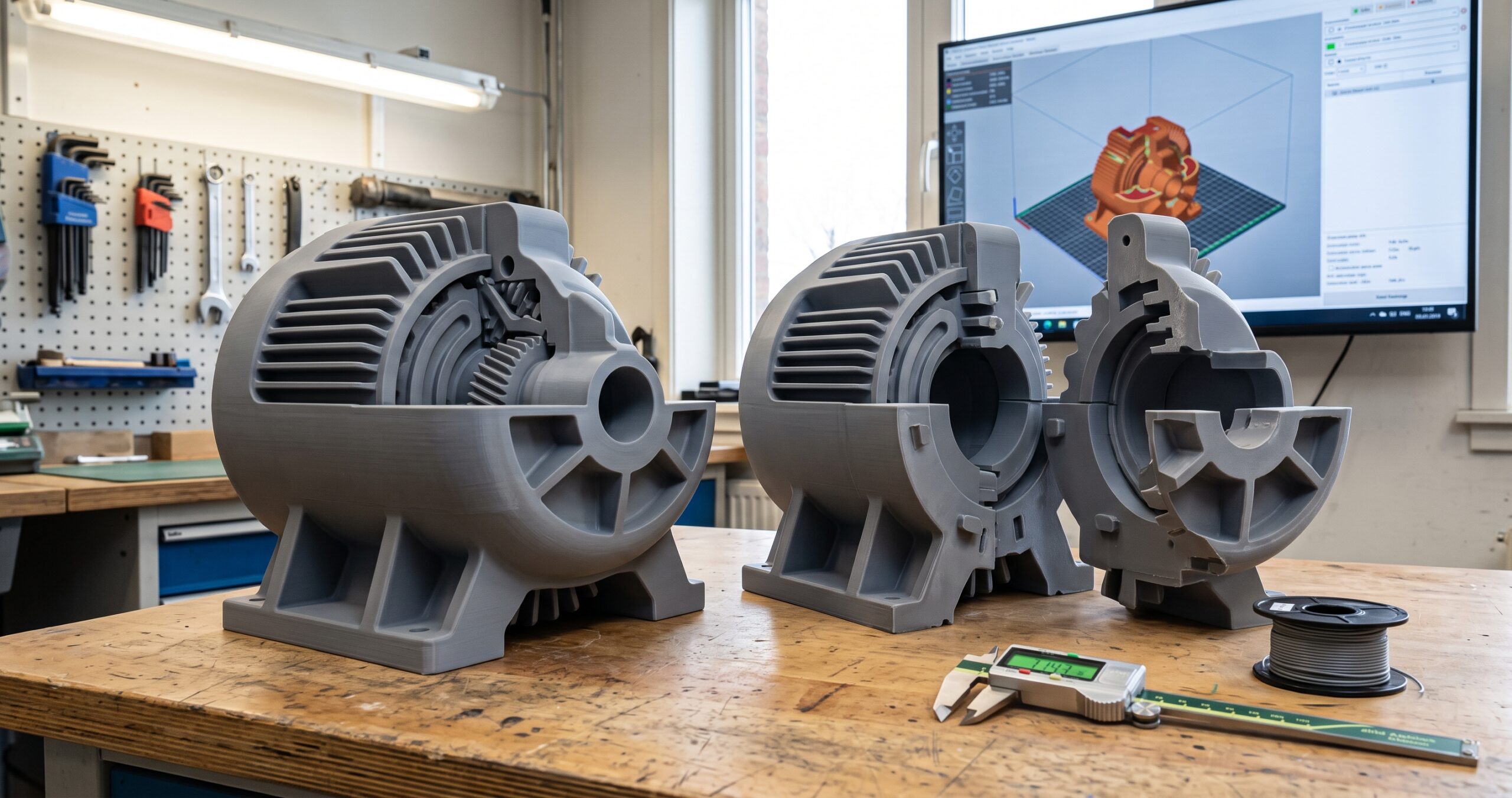
The right choice is therefore not “seamless at any cost.” It is the production plan that gives the finished object the best balance of fit, function, appearance, risk, and total labor.
Affiliate disclosure: This article may contain affiliate links. If you purchase through one of them, 3D Printing by Kevin may earn a commission at no additional cost to you. Recommendations are based on project fit, not compensation.
One-Piece vs. Split Large 3D Prints at a Glance
Before looking at joint shapes or slicer tools, compare the three realistic paths. The third option matters because some models should be redesigned as functional subassemblies instead of simply cut into arbitrary chunks.
| Decision | Best advantage | Main risk | Often fits |
|---|---|---|---|
| Print in one piece | No assembly seam or alignment step | A long print concentrates time and material in one attempt | Display shells, housings, fixtures, and shapes that orient cleanly |
| Split into keyed sections | Each section can be oriented, printed, inspected, and replaced separately | Joint fit, bonding, fasteners, and seam finishing add work | Large display models, props, covers, prototypes, and modular parts |
| Redesign as subassemblies | Part boundaries follow real functions, service points, colors, or materials | Requires more design work and clearer interface requirements | Functional equipment models, enclosures, demonstrators, and serviceable products |
This comparison gives us the three possible outcomes. Now we can examine the questions that determine which outcome is appropriate for a specific model.
Five Questions Decide Whether a Large 3D Print Should Be Split
Build volume is the obvious limit, but it is only one of five decisions. Answering all five prevents the common mistake of forcing a model into one piece merely because the slicer does not show an out-of-bounds warning.
1. What must the finished object do?
A presentation model and a load-carrying fixture can have the same dimensions but need completely different production plans. A display piece may prioritize hidden seams and smooth surfaces, while a functional part may prioritize load direction, fasteners, access, and repeatable alignment.
- Is it a visual model, fit-check prototype, enclosure, fixture, replacement part, or end-use component?
- Will anyone lift, flex, clamp, screw into, or repeatedly assemble it?
- Would a joint create a harmless cosmetic line or a critical failure point?
- Does the model need to come apart later for service, storage, or shipping?
Purpose defines the acceptable risk. With that established, the next question is whether the machine can accommodate the job in a practical orientation.
2. Does it fit with working room, not just nominal room?
A printer’s stated X, Y, and Z dimensions describe its nominal build volume. The actual job must also accommodate the chosen orientation, any brim or support structures, machine-specific exclusion areas, and the clearances shown in the final slicer preview.
A model that touches the limit in one axis deserves closer review. Rotating it diagonally may help, but that rotation can increase height, change support requirements, move a visible surface against the build plate, or place the layer direction across a load path.
For more context on the machines built for this work, see Large-Format 3D Printers: A New Tool for Home and Studio Prosumer Projects.
Once physical fit is confirmed, orientation becomes the next and often more important constraint.
3. Which orientation protects strength and visible surfaces?
FDM parts are built layer by layer, so their behavior is direction-dependent. A shape that fits vertically may place tension across layer bonds. The same shape laid down may align its layers more favorably but require more support or leave marks on an important face.
Support removal can also damage edges, holes, lettering, and cosmetic surfaces. Splitting the model may let each section rest on a flat, hidden cut face and keep its most important surface facing away from supports.
The Protolabs Network FDM design guide explains how orientation, bridges, holes, and supports affect printable geometry. Those process limits should be evaluated before a cut line is chosen.
After orientation, the model needs a deliberate seam location rather than an arbitrary slicer cut.
4. Where can a seam safely disappear?
A good split follows the design. Natural panel lines, changes in color, existing flanges, interior faces, and low-stress regions can hide or protect a joint. A straight cut through the center of the most visible curved surface usually creates unnecessary finishing work.
For a functional model, trace the expected load path before placing the split. Avoid putting a simple adhesive seam where bending, peeling, or repeated impact will try to open it. A mechanical joint, backing plate, or redesigned subassembly may be more appropriate.
A seam that works structurally must still work during assembly, which leads to the final question.
5. How will the sections be aligned, joined, finished, and moved?
“Glue it later” is not a complete assembly plan. The model needs a defined alignment method, intentional clearance, a material-compatible joining method, enough access to complete the joint, and a way to hold the sections while the connection is secured.
Transportation matters too. One large, rigid model may be harder to protect in a vehicle or shipping carton than several replaceable sections. On the other hand, a customer who needs a presentation-ready object may reasonably prefer professional assembly before delivery.
One strong rule: If splitting the model does not improve printability, function, finishing, serviceability, or delivery, the added joints may not earn their place. If keeping it whole forces a poor orientation or concentrates too much risk in one attempt, “seamless” may be the weaker plan.
These five answers reveal when seamless construction is worth the risk and when segmentation is the more controlled choice.
When Printing the Model in One Piece Is the Better Choice
One-piece printing is valuable when it removes a real problem, not simply because “one piece” sounds more professional. The strongest case combines suitable size, sensible orientation, manageable supports, and a meaningful reason to avoid joints.
A one-piece plan is often worth considering when:
- The complete model fits with practical margin in the final orientation.
- The best print orientation also supports the required strength and surface finish.
- A seam would cross a high-stress, sealing, locating, or highly visible area.
- The geometry has a stable footprint and a controllable warping risk.
- Post-processing tools can reach every support and surface that needs attention.
- The finished object can be handled, packaged, and delivered safely.
The hidden cost of “just make it seamless”
A long one-piece print creates concentrated risk. If a support collapses, an edge lifts, filament feeding becomes inconsistent, or a late layer shift occurs, the complete job may need to restart. The severity depends on the geometry, material, machine, and stage of failure.
Large flat areas can also magnify thermal movement, while tall narrow parts may be vulnerable to vibration or instability. These are not automatic reasons to split the model, but they belong in the quote and production review.
If those risks outweigh the value of a seamless shell, a controlled split can improve the overall result.
When Splitting a Large 3D Print Works Better
Segmentation is not merely a workaround for a small printer. Used deliberately, it can turn one difficult build into several easier, testable operations.
Splitting is often the better plan when it allows you to:
- Improve orientation: Place each section so its important surfaces and load directions receive better treatment.
- Reduce supports: Use flat cut faces as build surfaces and keep support marks away from visible detail.
- Limit failure exposure: Reprint one damaged section instead of restarting the entire model.
- Schedule sections efficiently: Use more than one suitable machine when profiles, material, and quality controls are coordinated.
- Combine colors or materials: Turn visual or functional boundaries into intentional part boundaries.
- Simplify transport: Pack protected sections and assemble them at the final location when the project allows it.
- Make the model serviceable: Use removable fasteners where internal components may need future access.
Those benefits come with added responsibilities. Every new section creates another file to identify, face to inspect, interface to test, and joint to assemble.
The Formlabs guide to printing models larger than a build volume likewise treats splitting, alignment features, labeling, bonding, and finishing as one connected workflow. Although its worked example focuses on resin printing, the planning principle also applies to FDM: segmentation changes the entire production process, not just the file size.
With the tradeoff clear, the next step is choosing a joint that matches the finished model.
Which Joint Should Connect the Printed Sections?
The best joint is not the most complicated one. It is the simplest interface that provides the needed alignment, strength, appearance, and serviceability on the actual printer and material.
| Joint approach | What it does well | What must be tested | Practical use |
|---|---|---|---|
| Flat butt joint | Simple cut and large flat bonding face | Manual alignment, sliding during cure, and resistance to sideways force | Low-load displays and seams supported by an internal plate |
| Pin and socket | Locates two sections and reduces assembly guesswork | Pin strength, hole size, clearance, insertion direction, and trapped adhesive | Display models, props, covers, and moderate-size shells |
| Step or lap joint | Adds overlap, alignment, and bonding area | Warping, clearance across the full overlap, and whether the step remains printable | Panels, enclosures, long covers, and finished display sections |
| Tongue, groove, or dovetail | Provides defined alignment and can resist movement in selected directions | Print orientation, entry path, friction, corner accuracy, and removal needs | Modular assemblies and parts designed for guided installation |
| Mechanical fasteners | Creates a serviceable connection and avoids relying only on adhesive | Wall thickness, boss design, insert or nut access, torque, and load spreading | Functional enclosures, equipment models, fixtures, and removable panels |
| Hidden backing plate or spine | Aligns broad surfaces and moves reinforcement behind the visible seam | Internal access, adhesive or fastener clearance, and added thickness | Large panels, signs, architectural models, and display shells |
No chart can supply a universal clearance for every FDM joint. Nozzle size, extrusion width, material, orientation, shrinkage, cooling, first-layer behavior, machine condition, and post-processing can all change the result.
Print a small interface coupon before committing to every section. The process in Why Doesn’t My 3D-Printed Part Fit? explains why testing the risky connection is more useful than guessing from a universal tolerance chart.
Joint geometry is only half of the assembly. The material and connection method must also agree with the model’s purpose.
Adhesive, Fasteners, or a Removable Assembly?
An adhesive that works on one plastic, surface condition, or load case may perform poorly on another. Before bonding a customer part, confirm the printed material, read the adhesive manufacturer’s technical and safety information, prepare the surface as directed, and test representative scrap or coupons.
Use this functional comparison to define the joining strategy:
- Permanent adhesive assembly: Useful when the seam should disappear and future disassembly is unnecessary. Surface preparation, clamping, cure time, gap behavior, and material compatibility must be controlled.
- Screws, captive nuts, or threaded inserts: Useful when the assembly must be opened, transported in sections, or serviced. The surrounding printed geometry must be designed for the hardware and expected tightening force.
- Guided friction fit: Useful for removable covers or presentation models when the joint has been tested through repeated assembly. A fit that works once is not proof of long-term durability.
- Hybrid joint: Pins or steps provide alignment while adhesive or fasteners provide retention. This separates the job of locating the parts from the job of holding them together.
For projects involving safety, pressure, food contact, medical use, high heat, structural loads, or failure that could injure someone, a casual adhesive joint is not an acceptable assumption. The complete application requires appropriate engineering review and validation.
Printing your own sections? Keep the material, color, drying condition, nozzle, machine profile, orientation, and inspection method controlled across the complete set.
Material option: Compare current filament choices through COEX 3D. Use code 3DPRINTINGBYKEVIN for 15% off.
Build-volume option: If a larger machine could eliminate difficult seams, compare current models through the Creality Official Store. Confirm the usable build area, supported materials, and final slicer fit before choosing a printer for the project.
Once the joint and material are defined, the real comparison shifts from printer time to total project time.
Which Option Costs Less: One Long Print or Several Sections?
One-piece printing can reduce file preparation, labeling, test-fitting, hardware, bonding, and seam finishing. However, a difficult one-piece orientation may require more supports, occupy a machine longer, and expose the entire job to a single late failure.
Splitting can reduce support waste and make individual sections easier to inspect or replace. It can also add substantial design, setup, assembly, clamping, curing, sanding, filling, painting, and quality-control labor.
That is why a serious quote considers the complete workflow:
- File review and repair
- CAD splitting and joint design
- Test coupons and fit adjustments
- Material and machine setup
- Support material and cleanup
- Printer occupancy and failure exposure
- Section labeling and inspection
- Assembly hardware, bonding, and cure time
- Seam finishing, paint preparation, and final presentation
- Packaging, pickup, or shipping
The cheapest-looking print plan can therefore become the more expensive finished model. A fair comparison ends at delivery-ready condition, not when the nozzle stops moving.
If the project requires multiple copies, approve one complete assembled model before the full run. Use Before You Order 100 3D-Printed Parts: Test One Part First to define the first-article and inspection plan.
With total cost framed correctly, you can turn the decision into a repeatable project planner.
Use the P.R.I.N.T. One-Piece-or-Split Planner
The P.R.I.N.T. Method keeps the printer from becoming the first decision. Complete these five steps before the model is separated or the quote is approved.
P: Problem
Write one sentence describing the finished result. Is the goal a presentation model, fit-check prototype, functional cover, replacement component, prop, fixture, or production-ready assembly?
R: Requirements
Record the finished dimensions, scale, deadline, quantity, surface expectations, color, environment, expected load, movement, transport needs, and consequence of failure.
I: Interfaces
Mark every seam, locating feature, fastener, mating surface, moving area, visible face, reference point, and feature that must remain accessible after assembly.
N: Next-Best Materials and Methods
Compare one-piece orientation, keyed segmentation, and functional subassemblies. Choose the material, layer direction, joint, printer, support plan, finish, and assembly method as one system.
T: Test and Tune
Print the smallest useful evidence first. Test a joint coupon, a detailed surface section, a critical hole or fastener boss, and one complete assembled first article before repeating the job.
Final pre-print checklist
- Confirm the final assembled size and measurement units.
- Open the model and verify that all bodies are present and at the intended scale.
- Preview the best one-piece orientation with supports and build-plate boundaries visible.
- Identify natural seam lines and low-risk cut locations.
- Choose how each section will align, remain secured, and be held during assembly.
- Print and measure the joint coupon using the intended printer, nozzle, material, and orientation.
- Label every section in the file set, slicer, inspection record, and assembly plan.
- Dry-fit the complete model before applying adhesive or final hardware.
- Inspect the finished assembly for dimensions, rocking, gaps, misalignment, finish, and service access.
- Approve one finished example before producing additional copies.
For a broader system covering files, slicers, materials, calibration, replacement parts, and troubleshooting, continue with P.R.I.N.T. It: Practical 3D Printing for Beginners.
The planner defines the manufacturing decision. A clear quote packet makes that decision easier to evaluate.
What to Send With a Large-Model Quote Request
You do not need to decide on every seam before asking whether the project is possible. Send enough information to compare the production paths honestly.
- The model file, preferably with editable or STEP geometry when mechanical changes may be needed
- The required finished length, width, height, scale, and units
- A reference image showing the complete assembled object
- A plain-language description of what the model must do
- Whether one-piece construction is required or simply preferred
- The surfaces that must look their best
- Expected handling, load, movement, heat, sunlight, moisture, or chemicals
- Color, finish, paint, labeling, and assembly expectations
- Quantity and deadline
- Delivery, local pickup, shipping, or on-site assembly needs
- Confirmation that you own the design or have permission to reproduce it
If you are unsure which file to send, use STL vs. STEP vs. 3MF: Which File Should You Send for 3D Printing?. A STEP file is often the better starting point when joints, wall thickness, fastener features, or cut locations may need revision.
Need a Large Model Reviewed Before You Commit?
Send the file, finished dimensions, intended use, quantity, and surface expectations. I can review whether the model should remain one piece, be divided into keyed sections, or be redesigned as a practical assembly.
Before the final recommendation, use the following knowledge check to test the reasoning behind the decision.
Four-Question Knowledge Check
Choose your answer before opening each explanation.
1. A model fits inside the printer’s stated build volume. Does that prove it should be printed in one piece?
Answer: No. The final slicer preview, orientation, supports, strength direction, visible surfaces, failure exposure, finishing, and transport requirements still need review.
2. Why can splitting improve a model that already fits on the machine?
Answer: Separate sections can receive better orientations, cleaner visible surfaces, fewer supports, controlled inspection, easier reprints, different materials, or safer transport.
3. What should be printed before every section of a keyed assembly?
Answer: Print a representative joint or interface coupon with the intended machine, nozzle, material, profile, and orientation. It can reveal clearance and assembly problems before the full model consumes time and material.
4. When should a large model be redesigned as subassemblies instead of merely sliced into equal pieces?
Answer: Redesign it when part boundaries should follow functions such as service access, fasteners, colors, materials, movement, load paths, removable panels, or transportation.
The quiz reinforces the central lesson: the best part count comes from the finished object’s requirements, not from a single dimension.
Frequently Asked Questions
Do large 3D prints have to be made in one piece?
No. Large objects are often divided into printable sections and assembled afterward. A well-designed split can improve orientation, support access, surface quality, repairability, and transport, but it also requires tested joints and a defined assembly plan.
Is a one-piece 3D print always stronger?
No. Removing a joint eliminates one possible weak area, but the one-piece orientation may place layers poorly relative to the load or require geometry that prints less reliably. Strength depends on the design, material, orientation, process, joint, and actual use.
What is the best way to hide a seam in a large 3D-printed model?
Place the split along an existing edge, panel line, color change, interior face, or other natural visual boundary. Use alignment features, dry-fit the sections, and plan filling, sanding, priming, or painting before production begins. The best approach depends on the material and finish requirement.
Can a 300 mm model be 3D printed in one piece?
Possibly, but the overall length alone is not enough to decide. The complete X, Y, and Z dimensions, orientation, supports, printer clearance, geometry, material, finish, load, and delivery requirements must be reviewed in the slicer. A model near 300 mm may fit one machine and need segmentation on another.
Those answers bring the comparison back to one practical rule.
The Best Large 3D Print Is Designed Around the Finished Job
A seamless model can be the right answer. A carefully keyed assembly can also be the better-engineered result. The goal is not to maximize size, minimize part count, or eliminate every visible line without considering the consequences.
Start with the finished purpose. Compare realistic orientations. Place seams deliberately. Test the smallest risky interface. Then approve the complete assembly before repeating it.
If your project needs design refinement, fit checks, finishing, or a controlled small batch, explore Precision 3D Printed Parts or use the project intake form to start with the files and information you already have.
Technical reference note: This article was checked against current large-model and FDM design guidance from Formlabs, Protolabs Network, and Bambu Lab. Machine capabilities, slicer features, materials, and adhesive instructions can change. Verify the documentation for the exact printer, slicer version, filament, hardware, and joining product used for the project.

What is the largest model you have tried to print? Tell me in the comments whether you attempted it in one piece, split it into sections, or changed the design. Include the problem that gave you the most trouble: build volume, warping, support marks, joint fit, visible seams, bonding, or transport. Your experience may help another reader plan the next large project more carefully.