
Functional 3D Printing • Sliding Fits • Practical Testing
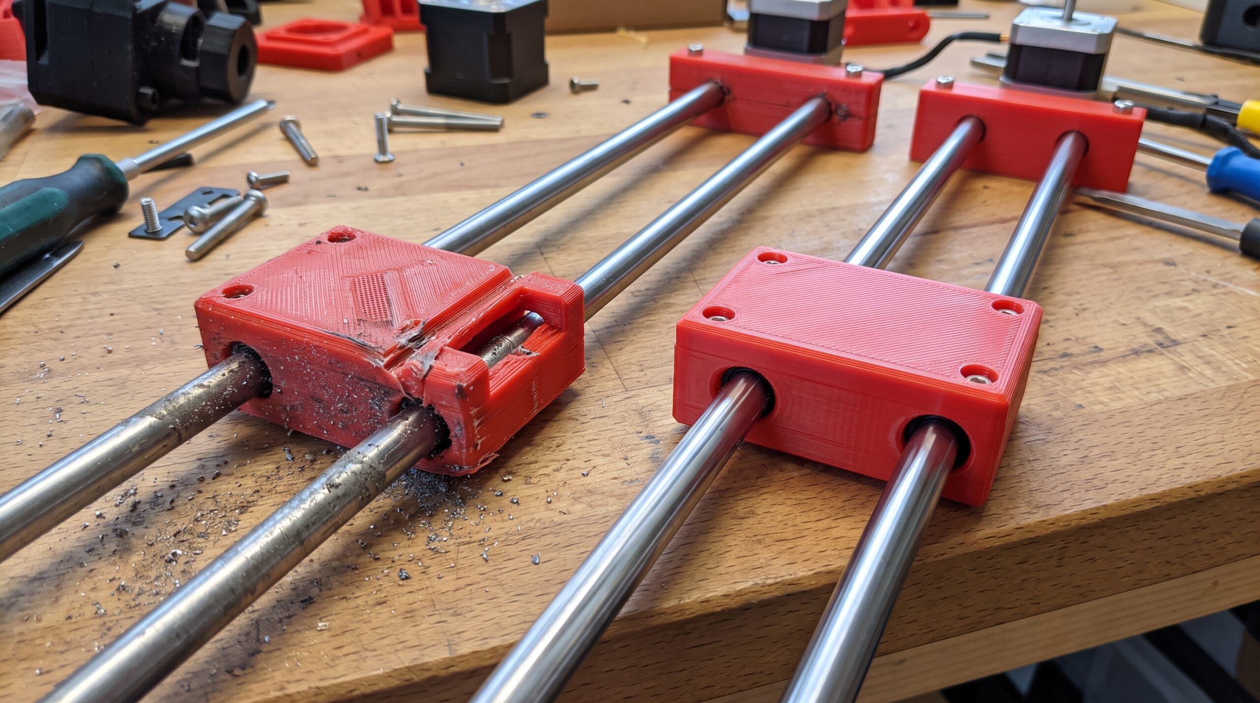
The slider moved when you first assembled it. Then you tightened the screws, added a little weight, or pushed it near the end of its travel—and it stuck. Another version may glide freely but knock from side to side every time it changes direction.
That is the frustrating middle ground of a 3D-printed sliding fit: loose enough to assemble, but not controlled enough to work reliably.
Quick Answer
A 3D-printed slider usually sticks because its running clearance is too small, its rails are not parallel, the first layer or seam intrudes into the path, or the moving part twists under load. Rattling usually means too much clearance or too little guiding length. A jam that occurs only at one location points toward local distortion, debris, a surface defect, or alignment changing along the travel.
Do not enlarge every surface at once. Mark the rub points, test the slider through its full travel under the real load, and change one controlled feature before printing the whole assembly again.
“It Moves” Is Not the Same as “It Slides Correctly”
A useful sliding fit has to do more than pass an assembly test. It must move through the intended stroke, stay aligned, carry the expected load, tolerate normal print variation, and continue working after repeated cycles.
The clearance shown in CAD is only the starting point. The printed result is affected by extrusion width, cooling, material shrinkage, first-layer spread, seam placement, support contact, orientation, and the calibration of the specific printer. A long rail can also magnify a small angular error that seems harmless on a short test piece.
This is why copying a nominal gap from someone else’s design can be misleading. A value that works for a short PLA drawer on one machine may fail on a long PETG guide printed in another orientation.
Start With the Symptom: Stick, Rattle, or Jam?
It sticks everywhere
The running fit may be consistently too tight, or broad surfaces may be rubbing. Check dimensional error, first-layer flare, seam bumps, and whether the mating geometry leaves room for normal print variation.
It rattles or rocks
The fit may have too much clearance, too little engagement length, or only two small contact points. The answer may be better guiding geometry—not simply shrinking the gap everywhere.
It jams in one spot
Look for a rail that bows, changes width, carries a seam or blob, or becomes misaligned after mounting. A localized jam is evidence; mark the position before sanding anything.
Seven Reasons a 3D-Printed Slider Fails
1. The Clearance Exists in CAD but Disappears in the Print
Internal channels can print smaller and external rails can print larger than their modeled dimensions. Corners may also become slightly rounded or swollen. If both mating parts shift toward each other, a modest CAD clearance can vanish.
Measure the actual rail and channel at several locations. Do not rely on a single reading at an easy-to-reach end. If the gap is uncertain, print a short labeled clearance coupon with the same printer, nozzle, material, layer height, orientation, and slicer profile planned for the real part.
2. First-Layer Expansion Creates a Hidden Brake
The first layer needs enough compression to adhere, but excessive spread can create an “elephant foot” along the bottom edge. On a sliding part, that thin lip can act like a brake even when the rest of the geometry measures correctly.
Inspect the lower edges under strong light. If the interference is limited to the first few layers, correct the first-layer process or add a deliberate edge relief where appropriate instead of loosening the entire guide.
3. The Rail and Channel Are Not Truly Parallel
Two features can each measure correctly and still bind if they are not parallel. A small taper across a long travel progressively removes clearance. Mounting screws can also pull a flexible printed rail out of line after it worked perfectly on the bench.
Test the parts before and after mounting. If tightening the hardware changes the motion, inspect the mounting faces, screw sequence, base flatness, and whether the design needs locating features that establish alignment without forcing the fasteners to do it.
4. The Slider Tips Under Load
A slider pushed near its center may move smoothly. Apply force above, below, or to one side of that centerline and it can rotate slightly, driving opposite corners into the guide.
This is a geometry problem as much as a clearance problem. A longer bearing length, wider guide spacing, better load location, or an additional guiding surface may control the moment more effectively than adding a large loose gap.
5. A Seam, Support Scar, or Blob Sits in the Travel Path
One raised seam can cause a repeatable click or jam. Support residue inside a channel can do the same. If the slider stops at the same position every time, inspect that exact location before changing the model.
Use the slicer preview to see where seams begin and end. Reorient the part or place the seam on a non-bearing surface when possible. Avoid treating heavy sanding as the complete solution; uncontrolled material removal can turn a local defect into permanent wobble.
6. Broad Flat Surfaces Create More Friction Than Expected
Large mating faces may look stable, but they can magnify small waves, debris, and dimensional variation. They also provide more opportunity for friction and stick-slip motion.
Purposeful bearing pads, rails, ribs, or replaceable wear points can define where contact should occur. The objective is not always maximum surface contact. It is predictable contact that supports the load without overconstraining the motion.
7. Heat, Wear, and Debris Change the Fit
A slider that works when clean and cool may behave differently after repeated cycling. Printed surfaces can polish, shed particles, pick up dust, deform under sustained side load, or expand in a warmer environment.
Material choice matters, but no filament label guarantees a good bearing system. Test the exact geometry in the expected temperature, load, speed, and environment. If failure could damage equipment or injure someone, a printed plastic-on-plastic slide may not be the appropriate final mechanism.
Comparison: Match the Fix to the Evidence
| What you observe | Likely area to inspect | Better first test | Common wrong response |
|---|---|---|---|
| Tight through the full travel | Overall printed dimensions, channel size, rail size, first-layer flare | Short clearance coupon in the final orientation | Sand every surface until it moves |
| Free at one end, tight at the other | Taper, bow, parallelism, cooling distortion | Measure at multiple stations and reverse the slider | Add one large global clearance |
| Jams at the same exact position | Seam, blob, support scar, debris, local rail damage | Mark the stop point and inspect the corresponding surfaces | Change the entire CAD model first |
| Works unloaded, binds under force | Moment load, short engagement, guide spacing, flexible walls | Apply the real load at its real location | Lubricate without correcting geometry |
| Moves freely but rattles | Excess clearance, short bearing length, poorly defined contact | Check angular play at both ends of travel | Reduce every dimension equally |
| Worked before mounting | Base flatness, screw sequence, mounting-face distortion | Cycle it after each fastener is tightened | Assume the printed fit changed by itself |
The Sliding-Fit Planner: Record the Job Before Changing the Gap
Use this compact planner before opening the CAD file. It prevents a common mistake: changing dimensions without knowing which behavior you are trying to improve.
- Motion: How far must it travel, and does it need to move freely, hold position, or return?
- Load: What weight or side force acts on it, and where is that force applied?
- Environment: Will dust, moisture, heat, sunlight, vibration, or chemicals reach the guide?
- Contact: Which surfaces are intended to guide, and which should never rub?
- Production setup: Which printer, material, nozzle, layer height, orientation, and slicer profile will be used?
- Success test: How much play is acceptable, how many cycles will you test, and what counts as a jam?
If you are still separating tolerance from functional clearance, start with 3D Printing Tolerances Explained. If the assembly fits but rocks or works loose, continue with Why 3D-Printed Parts Fit but Still Wobble.
Apply Kevin’s P.R.I.N.T. Method™
Problem: Name the symptom precisely. Does it stick everywhere, jam at one position, rock under load, or change after mounting?
Requirements: Define travel, load, speed, allowable play, cycle count, environment, service life, and consequences of failure.
Interfaces: Mark the intended bearing surfaces, end stops, fasteners, mounting faces, load point, and every location where misalignment can enter the system.
Next-Best Materials & Methods: Choose geometry, orientation, contact strategy, material, hardware, and production method that suit the real job—not merely the easiest print orientation.
Test & Tune: Print the smallest representative section, record the result, revise one variable, and repeat before committing to the complete assembly or batch.
A Seven-Step Test That Protects Your Next Print
- Clean without reshaping. Remove loose strings and debris, but do not sand away the evidence yet.
- Cycle the unloaded part slowly. Note whether resistance is constant, directional, or localized.
- Mark contact points. Look for polishing, whitening, scratches, transferred dust, or raised print features.
- Measure along the travel. Check the rail and channel at several stations, not just one end.
- Repeat after mounting. Tighten fasteners in stages and cycle the motion after each change.
- Apply the representative load. Push from the real handle or attachment point instead of the most convenient spot.
- Print a controlled coupon. Compare a small range of purposeful clearances or contact features using the final process.
Prusa’s current guidance on modeling with 3D printing in mind reinforces the larger point: printable geometry depends on orientation, overhangs, bridging, nozzle behavior, and the chosen machine. For sliding fits, those production decisions become part of the mechanism.
When Lubrication Helps—and When It Hides the Problem
A material-compatible lubricant may reduce friction in a suitable mechanism, but it cannot make crooked rails parallel, remove a seam bump, add missing bearing length, or prevent a flexible slider from tipping.
Before applying anything, confirm compatibility with the exact plastics, surrounding equipment, temperature, dust exposure, and intended use. Some lubricants can attract debris, affect finishes, or interact poorly with particular polymers. Follow the current instructions from the material and lubricant manufacturers.
Use lubrication as one part of a validated design—not as the first response to unexplained binding.
Choosing Material Without Asking It to Fix the Geometry
PLA, PETG, ABS, ASA, nylon, and filled materials can all behave differently in a sliding application. Stiffness, toughness, heat resistance, moisture response, surface texture, and creep may matter. But a premium material cannot repair a tapered channel or a short guide that tips under load.
Choose the material after defining the job and test it in the final geometry. If you are comparing U.S.-made filament options, explore COEX 3D filament and use code 3DPRINTINGBYKEVIN for 15% off. Confirm the code and current terms at checkout.
Affiliate disclosure: If you purchase through the COEX link, 3D Printing by Kevin may earn a commission at no additional cost to you. Material recommendations should follow the project requirements and test results, not the discount.
Need the Slider Designed Around the Real Job?
A useful quote starts with the motion, dimensions, load, mounting method, environment, and the object the part must fit—not simply a photo of the broken piece.
Build the Whole Part Around Better Decisions
P.R.I.N.T. It: Practical 3D Printing for Beginners brings Kevin’s complete planning method into one structured guide. Use it to work from the real problem through requirements, interfaces, materials, printing, testing, and revision.
If you are new to the process, begin with the free step-by-step beginner guide. The goal is not to guess the perfect clearance once. It is to build a repeatable way to learn from the print in front of you.
Four-Question Practical Knowledge Check
Choose your answer before opening each explanation.
1. A slider jams only near the end of its travel. Should you immediately enlarge the entire channel?
Answer: No. A repeatable local jam points first toward a seam, surface defect, debris, taper, bow, or alignment change at that position. Preserve and inspect the evidence before making a global change.
2. The slider works loose on the bench but binds after installation. What should you inspect first?
Answer: Check mounting-face flatness, rail parallelism, screw sequence, base distortion, and whether the fasteners are pulling the guide out of alignment.
3. Will adding more clearance always stop a loaded slider from binding?
Answer: No. If the applied force tips or twists a short slider, more clearance may increase angular movement and make corner binding worse. Bearing length, guide spacing, stiffness, and load position may need attention.
4. Why print a short clearance coupon in the final orientation?
Answer: It tests how the intended printer, material, nozzle, layer height, orientation, and slicer profile reproduce the critical interface without wasting the time and material required for the complete assembly.
Frequently Asked Questions
How much clearance should a 3D-printed slider have?
There is no universal gap that works for every printer, material, orientation, slider length, and load. Begin with a representative clearance coupon, measure the printed result, and validate the complete mechanism under realistic conditions.
Why does my slider move in one direction but stick in the other?
Directional resistance can come from a seam or surface feature with a sharp edge, a slider that tips differently when pushed versus pulled, a tapered guide, or a load applied away from the guide’s center. Mark the contact points during both directions.
Should I sand a 3D-printed sliding surface?
Light, controlled finishing may be appropriate for a known surface defect, but sanding before diagnosing the contact can erase useful evidence and introduce uneven clearance. Correct repeatable geometry or process errors at their source when practical.
Can PETG be used for a 3D-printed slider?
PETG may suit some noncritical sliding parts, but suitability depends on the exact grade, geometry, surface contact, load, heat, speed, environment, and expected life. Test the actual assembly rather than relying only on the material name.
Can Kevin make a custom slider or guide without an STL file?
Potentially, yes. Start with photos, dimensions, travel, load, mounting details, the mating objects, and an explanation of what the mechanism must do. Use the project intake form so the job can be evaluated before a production route is recommended.
What Is Your Slider Doing?
Does it bind through the full travel, jam in one spot, rattle under motion, or change after you tighten the mounting screws? Share the symptom and material in the comments. A precise description often reveals more than “the clearance is wrong.”
Safety note: This guide is for general educational use. Sliding components used in safety-critical, load-bearing, high-temperature, food-contact, medical, automotive, electrical, or machinery applications require application-specific engineering, materials, testing, guarding, and compliance review.
