
Functional 3D printing • Moving joints • Replacement parts
The hinge came off the build plate looking clean. The pin went in. The two halves moved. Then the real problems started: it tightened at one angle, rattled at another, and a thin knuckle split after a few cycles.
A hinge that moves once is not automatically a successful hinge. It still has to stay aligned, carry the intended load, reach the required angle, resist wear, and stop without forcing the smallest printed feature to absorb every mistake.
When I review a functional hinge, I do not begin by adding infill. I begin with the interfaces: the pin, the bore, the knuckles, the gaps, the mounting faces, and the path the load follows when the assembly opens and closes.
Quick Answer
A 3D-printed hinge usually binds because its bores are too tight, its knuckles are misaligned, or printed variation leaves too little axial and radial clearance. It wobbles when those gaps are too large, the pin bends, or the joint lacks support. It snaps when the knuckle root, layer direction, hard stop, or load path concentrates force in a weak area.
For a serviceable functional part, a separate smooth metal pin is often the most forgiving starting point. Print-in-place hinges can be convenient for light-duty work, while printed pins, shoulder bolts, captured fasteners, and living hinges each solve different problems. There is no universal clearance that works on every printer and material—test the actual joint before printing the full part.
First Identify the Failure You Actually Have
“The hinge does not work” is too broad to guide a useful revision. Binding, wobble, and breakage point toward different causes, and one fix can make another symptom worse. Enlarging a bore may free a binding pin, for example, but it can also create more play than the assembly can tolerate.
It binds
Look first: bore size, pin straightness, knuckle alignment, elephant foot, support scars, and axial gaps.
Do not assume: lubricant can correct a joint that is geometrically misaligned.
It wobbles
Look first: excessive clearance, short knuckles, long unsupported pin length, thin mounting faces, and flexible pin material.
Do not assume: every bit of play is harmless once load and leverage are added.
It snaps
Look first: sharp knuckle roots, thin walls, layer direction, a missing travel stop, impact, and load applied away from support.
Do not assume: a higher infill percentage repairs a poor load path.
A Reliable Hinge Is Four Interfaces Working Together
The visible hinge barrel gets most of the attention, but the joint is a small system. A precise bore cannot rescue mounting faces that twist out of alignment. A strong pin cannot rescue a thin knuckle root. A perfect print-in-place gap cannot rescue a design that uses the knuckles themselves as the end stop.
The four-part hinge check
Enough running clearance to move without uncontrolled play.
Knuckle bores share one practical axis after printing and mounting.
Force travels into supported walls, ribs, and mounting surfaces.
A deliberate surface limits rotation before the knuckles are pried apart.
The joint is only as dependable as the weakest interface under real use.
Print-in-Place, Separate Pin, Printed Pin, or Living Hinge?
The right hinge style depends on how the part will be assembled, serviced, loaded, and printed. Convenience matters, but so do repeatability and the consequences of failure.
| Hinge method | Often a good fit for | Main advantage | Main caution |
|---|---|---|---|
| Print-in-place pin and knuckles | Light-duty boxes, models, demonstrations, and assemblies that cannot be pinned later | Comes off the printer assembled | Clearance, bridging, first-layer effects, and trapped debris can make results printer-dependent |
| Separate smooth metal pin | Serviceable brackets, covers, fixtures, and moving replacement parts | Straight, wear-resistant pin that can be removed or replaced | The printed bores and pin-retention feature still require careful design |
| Printed removable pin | Prototypes, low-load hinges, oversized joints, and all-plastic assemblies | No purchased pin and easy geometry changes | Printed roundness, layer direction, bending, surface drag, and wear can limit performance |
| Shoulder bolt or screw pivot | Assemblies needing controlled pin diameter, retention, and convenient disassembly | Standard hardware can create a defined bearing surface | Clamping the joint too tightly can lock or crush the moving parts |
| Living hinge | Thin, flexible connections where the material and process are deliberately chosen for repeated bending | No separate pin or multi-part assembly | Material, thickness, print path, bend radius, and cycle requirements are unusually sensitive |
| Off-the-shelf hinge | Higher-cycle, higher-load, or easily serviced assemblies | Moves the wear interface into proven hardware | The printed part still needs strong mounting points and accurate alignment |
The best choice is not always the most printable choice. It is the method that meets the motion, load, service, and safety requirements with the least uncertainty.
Why a Separate Pin Is Often the Practical Baseline
A separate pin lets the printer make the housing while standard hardware provides the rotating shaft. That division of work is useful: the bores can be tested and adjusted without having to print the pin and hinge as one inseparable assembly.
A smooth metal pin can also reduce one source of variation. It will not have a seam, layer stair-stepping, or a slightly oval cross-section created by printing orientation. But it does not make the surrounding part automatically reliable. The knuckles can still split, the pin can walk out, and the mounting faces can still twist.
Plan the retention method before printing. Options can include a headed pin, a groove and clip, a captured end, a light press feature, a cotter-style keeper, or geometry that traps the pin after final assembly. The correct choice depends on access, load, service, and whether accidental removal would matter.
Kevin’s practical rule
If the hinge must be serviced, make the pin removable on purpose. If it must never work loose, design the retention on purpose. “It felt tight when I pushed it in” is not a retention plan.
Clearance Is a Test Result, Not a Number to Copy
The diameter entered in CAD is not the only thing controlling the finished gap. Nozzle size, line width, layer height, seam position, hole orientation, cooling, material behavior, machine calibration, and slicer compensation can all change the printed bore and pin.
That is why a clearance copied from another maker may be a useful starting hypothesis but not a promise. A horizontal hole may print differently from a vertical one. A short test coupon may cool differently from a large enclosure. A material change can alter both the fit and how the joint wears.
- Use the actual pin or fastener planned for the finished assembly.
- Print a short section containing the real bore orientation and wall structure.
- Test several controlled clearances in one coupon when practical.
- Check motion across the full angle, not only near the starting position.
- Record the machine, nozzle, material, orientation, and winning geometry.
If the entire part has fit problems—not only the hinge—start with 3D Printing Tolerances Explained. If the holes line up but the assembly still moves unpredictably, compare it with why fitted parts can still wobble.
Radial Clearance and Axial Clearance Solve Different Problems
Radial clearance is the working space between the pin and the bore. Too little can create friction or a press fit. Too much can let the leaf shift, tilt, or knock under changing load.
Axial clearance is the gap between neighboring knuckles or hinge leaves along the pin’s length. Too little can make the faces rub after printing variation or mounting distortion. Too much can let the moving part slide side to side.
They should be evaluated separately. Enlarging the bore does not correct knuckle faces that are rubbing. Increasing the gap between knuckles does not correct bores that do not share an axis.
Alignment Can Be Lost After the Hinge Leaves the Printer
A hinge can move freely in your hand and bind after installation. That often means the surrounding assembly is twisting the leaves or pulling the mounting faces out of plane.
- Mounting screws may draw a thin leaf against an uneven surface.
- A long printed panel may warp enough to shift the hinge axis.
- Two separately mounted hinge sections may be individually straight but not coaxial.
- A fastener tightened near the barrel may distort the bore.
- A support scar or first-layer flare may interfere only after the joint is fully seated.
Test the hinge in the mounted condition whenever the surrounding structure can change its alignment. A useful assembly check includes the actual screws, contact surfaces, opening angle, and expected direction of force.
Design the Knuckle Root for the Load
Many broken hinges fail where the round knuckle blends into the flat leaf. A sharp inside corner concentrates stress. A thin wall leaves little material around the bore. A long lever arm multiplies the force reaching that small root.
Better revisions may include:
- a generous transition or fillet at the knuckle root;
- more perimeter material around the bore;
- a wider leaf or rib that carries force toward the mounting area;
- shorter unsupported distance between the load and the hinge;
- more knuckle length or a better-supported pin;
- a deliberate stop surface that absorbs opening force away from the barrel; and
- an orientation that does not ask weak interlayer bonds to resist the dominant prying force.
If a part is separating at layer boundaries, continue with why more infill may not fix layer-line failure. If the trouble begins around mounting hardware, use the screw-cracking guide before revising the hinge barrel alone.
Do not let the knuckles become the hard stop
When the hinge reaches its maximum angle, another broad surface should stop the motion whenever practical. If the barrel or thin knuckle edge takes the impact, every forceful opening becomes a pry test at the smallest feature.
Print Orientation Changes More Than Surface Finish
Orientation affects bore shape, support contact, seam placement, and the direction in which the knuckles are built. It also changes which printed paths carry the opening load.
There is no universal “always print a hinge this way” rule. A barrel printed vertically may produce clean circular layers but place another feature in a poor direction. A barrel printed horizontally may need support or bridge tuning. A complete enclosure may force compromises that a separate hinge leaf would avoid.
Compare orientations against the job:
| Question | Why it matters | What to test |
|---|---|---|
| Will the bore need support? | Support scars can create a tight spot or rough bearing surface. | Inspect and gauge the full bore, not only the opening. |
| Which way will the leaf be pried? | The dominant load may pull across layers or along continuous paths. | Load a representative coupon in the real direction. |
| Where will the seam land? | A seam inside a small bore can create a recurring high spot. | Review the sliced toolpath and rotate the seam if useful. |
| Will the mounting face stay flat? | Warp or first-layer flare can shift alignment after assembly. | Mount the test part to the real mating surface. |
Material Matters—but It Cannot Correct the Wrong Geometry
Stiffness, toughness, friction, heat response, moisture sensitivity, and long-term deformation all affect a moving joint. A material that is excellent for an indoor prototype may not suit a warm enclosure, outdoor latch, constantly loaded door, or high-cycle fixture.
Use published data as a comparison tool, then test the printed geometry. The Prusa Filament Material Guide lets readers compare characteristics such as mechanical suitability, temperature resistance, impact resistance, ultraviolet resistance, and flexibility. Those labels help narrow the field; they do not certify a particular hinge design.
Need filament for controlled test pieces?
Affiliate/partner disclosure: I may receive compensation from qualifying purchases at no additional cost to you.
Use the same filament brand, color, drying condition, and print profile for the coupon and final part whenever repeatability matters. You can shop through my COEX 3D partner page and use code 3DPRINTINGBYKEVIN for 15% off when eligible.
Test Motion, Load, and Wear in Stages
A free-moving hinge on the bench has passed only the first test. The fastest useful process adds difficulty one stage at a time, so a failure still tells you what changed.
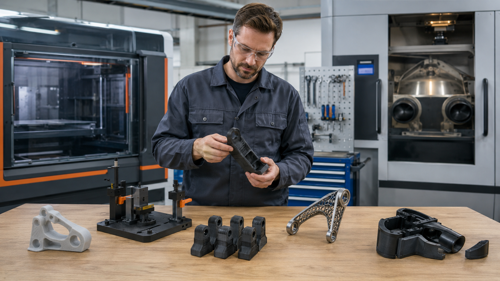
The National Institute of Standards and Technology emphasizes measurement and standards as additive manufacturing matures. At workshop scale, the practical version is simple: document the geometry and process, test a representative part, inspect the result, and change one meaningful variable at a time.
For a broader functional check after the hinge works, use these seven real-world durability tests. A hinge test should never create a new hazard; keep fingers away from pinch points and do not improvise high loads on a part whose failure could release stored energy.
P.R.I.N.T. Hinge Planner
Complete this before changing five settings and printing the entire assembly again. The blank lines are included so this section can be printed and used at the workbench.
Does it bind, wobble, walk sideways, wear, crack, or lose the pin?
Record angle, load, cycles, temperature, environment, expected life, and failure consequence.
Record pin diameter, bore direction, radial gap, axial gap, knuckle length, mounting faces, and stop.
Compare a metal pin, printed pin, shoulder bolt, print-in-place joint, living hinge, or purchased hardware.
Define the coupon, mounted test, cycle check, load direction, inspection points, and one variable to change.
What passed, what failed, and what evidence supports printing the complete part?
Keep the Complete Practical Workflow Beside Your Printer
P.R.I.N.T. It: Practical 3D Printing for Beginners connects measurements, material decisions, calibration, replacement-part planning, troubleshooting, and the complete P.R.I.N.T. Method™ in one structured reference.
A hinge problem is exactly where that process helps: define the real symptom, record the requirement, inspect every interface, choose the next-best method, and learn from a controlled test.
Explore the P.R.I.N.T. It ebookWhen a Printed Hinge Needs More Caution
A moving joint can pinch fingers, drop a cover, release a load, expose electrical parts, or let a guarded component move unexpectedly. Do not treat a successful desktop print as automatic approval for a safety-critical use.
Use an approved replacement, engineering review, verified hardware, a different material or manufacturing process, or a decision not to print when failure could cause injury, loss of control, dangerous electrical exposure, pressure release, fire, structural collapse, or serious equipment damage.
This is also where Kevin’s broader project approach matters. FDM may be a practical route for many covers, jigs, light-duty doors, replacement tabs, and noncritical mechanisms. Another job may be better served by machined hardware, molded material, a powder-bed process, or an off-the-shelf hinge.
Have a Broken Hinge or Moving Replacement Part?
Send clear photographs, basic measurements, the mating parts, the required opening angle, the expected load, and a description of how the original failed. Include the physical original or an authorized CAD file when available.
I can review whether the practical next step is a test coupon, a separate-pin redesign, a different material, purchased hardware, another manufacturing method, or a project that should not move forward as a printed replacement.
Start a Project Review Compare Threaded ConnectionsFour-Question Knowledge Check
Choose one answer for each question, then select Check my answers. The explanations stay visible after scoring.
Frequently Asked Questions
How much clearance should a 3D-printed hinge have?
There is no universal clearance that works across every printer, material, orientation, nozzle, and hinge size. Start with a small representative coupon, test the actual pin, and record the radial and axial gaps that work on your process. A hinge that needs controlled motion may also need less play than a light-duty lid.
Is a metal hinge pin better than a printed pin?
A smooth metal pin is often a practical choice for repeated movement, service, and a defined bearing surface. A printed pin can be useful for prototypes, oversized low-load joints, or all-plastic assemblies. The decision still depends on load, wear, environment, pin retention, and what happens if the joint fails.
Are print-in-place hinges strong enough for functional parts?
They can be useful for appropriate light-duty applications, but “printed assembled” does not prove long-term strength or wear performance. Test clearance, motion, load, cycle behavior, layer direction, and the end stop. For a serviceable or more demanding joint, a separate pin or purchased hinge may reduce uncertainty.
Why does my hinge move freely before mounting but bind after installation?
The mounting surfaces or screws may be twisting the leaves and shifting the bores out of alignment. Check surface flatness, screw torque, hole position, panel warp, first-layer flare, and whether the two hinge sections remain coaxial when fully installed.
Will more infill stop a hinge knuckle from snapping?
Not necessarily. The critical features are often the material around the bore, the knuckle root, wall paths, fillets, layer direction, lever arm, mounting support, and travel stop. Extra infill far from the failure may add print time without correcting the load path.
Should I lubricate a 3D-printed hinge?
Lubrication may reduce friction in a compatible joint, but it cannot correct a tight, rough, or misaligned bore. Confirm that any lubricant is compatible with the printed polymer, nearby materials, cleanliness requirements, and the application. Keep lubricant away from situations where contamination would be a problem.
When should I avoid using a 3D-printed hinge?
Avoid treating an unqualified print as a direct replacement when hinge failure could injure someone, release stored energy, drop a serious load, expose dangerous electrical parts, defeat a required guard, or cause major equipment damage. Use an approved part, engineering review, verified hardware, another process, or a decision not to print.

What Is Your Hinge Doing?
Does it bind at one angle, rattle along the pin, walk sideways, wear into powder, or crack at the knuckle root? Describe the material, pin type, orientation, and when the problem appears in the comment section. Your details may help another reader recognize the same failure before wasting a full print.