
A broken plastic part can be frustrating for a surprisingly simple reason: everything around it may still work perfectly.
The appliance, tool, cabinet, machine, or piece of equipment is fine. One clip snapped. One mounting boss cracked. One bracket split—and suddenly the whole thing becomes difficult or impossible to use.
That is where custom 3D printing replacement parts can become interesting. But the best approach is not always to copy the failed part exactly.
Sometimes the break is telling you something.
The Broken Part Is Evidence
When I evaluate a failed component, I do not look only at its outside shape. I want to know where it cracked, what was attached to it, which direction the load came from, and what conditions it experienced.
A clean break beside a screw hole tells a different story than a flexible tab that snapped after repeated use. A warped component near heat deserves a different response than a bracket that failed after an impact.
That distinction matters because simply making everything thicker is not engineering. Neither is choosing a tougher-sounding filament and hoping for the best.
The second approach is the one I prefer for functional work.
If you are deciding whether the damaged component is even a sensible candidate, start with my 3D print or replace a broken plastic part guide.
Copying a Part and Redesigning a Part Are Not the Same Job
There are times when matching the original geometry closely makes sense. Maybe the part fits inside a tight assembly, interfaces with several surrounding pieces, or contains dimensions that should not be changed.
Other failures leave room for improvement.
| Question | Direct Replacement | Function-First Redesign |
|---|---|---|
| Primary goal | Reproduce the original geometry. | Restore the required function. |
| Weak areas | May remain unchanged. | Can be investigated when the application allows it. |
| Mounting features | Usually matched closely. | Interfaces stay controlled while surrounding geometry may change. |
| Material | Selected to approximate the original need. | Selected around actual environment and use. |
| Testing | Checks whether the reproduction fits. | Checks fit, movement, retention, load path, and intended function. |
The trick is knowing which dimensions are negotiable and which ones absolutely are not.
My P.R.I.N.T. Method Starts Before the Printer
A replacement-part project fits naturally into the P.R.I.N.T. Method™ because the printer is only one part of the solution.
P — Problem: What failed, and what problem does that failure create?
R — Requirements: What load, movement, temperature, weather, vibration, appearance, lifespan, or other conditions matter?
I — Interfaces: What holes, shafts, clips, mounting faces, slots, mating curves, clearances, or fasteners have to work with something else?
N — Next-Best Materials & Methods: What combination of geometry, material, orientation, hardware, and manufacturing process makes sense?
T — Test & Tune: What needs to be physically verified before the design is considered finished?
This prevents the project from becoming “measure it, print it, hope it works.”
Step 1: Find Out Why the Original Part Failed
The break itself can provide clues.
- Did it crack beside a screw?
- Did a snap tab repeatedly flex until it broke?
- Did the part split along a thin section?
- Was the component exposed to heat or sunlight?
- Did something impact it?
- Was the original part already loose or misaligned?
- Was someone tightening a fastener when it failed?
The answer does not automatically tell me how to redesign the part, but it tells me where to look.
For example, a crack around a fastener may involve hole fit, boss thickness, installation force, geometry, or load direction—not simply insufficient infill. I cover that problem in more detail in Why 3D Prints Crack Around Screws.
Step 2: Measure the Interfaces Before the Cosmetic Details
A decorative curve can be slightly different and still work perfectly. A screw hole five millimeters out of position probably cannot.
That is why replacement-part measurement should focus first on the features that control fit and function.
You can use my guide to measuring a part for 3D printing to collect those dimensions systematically.
Step 3: Rebuild the Geometry in CAD
Some replacement parts are simple enough to recreate from caliper measurements and a few sketches. Others include curves, damaged surfaces, hidden features, or geometry that makes the process more involved.
Beginner-friendly tools such as Tinkercad can handle straightforward designs. For parametric modeling and more controlled dimension-driven work, FreeCAD is an open-source option.
A 3D scanner can also help capture complicated surface geometry, but scanning does not eliminate CAD. A mesh still may need cleanup, alignment, dimensional verification, feature reconstruction, and deliberate tolerances before it becomes a useful replacement part.
Step 4: Decide Whether the Weak Area Should Change
This is where “broken part to better design” becomes more than a catchy phrase.
If the application is appropriate and the surrounding assembly allows it, a redesign might explore changes such as:
- Smoothing an abrupt transition where stress appears concentrated.
- Adding material around a mounting feature when adequate clearance exists.
- Reconsidering a thin wall or narrow connection.
- Changing how a screw or insert interacts with the plastic.
- Adjusting print orientation so the expected load and layer structure are considered together.
- Changing a clip or tab geometry when repeated flexing caused the original failure.
Notice what is missing from that list: “set infill to 100%.”
More material inside a part does not automatically correct poor geometry, an unsuitable orientation, excessive fastener stress, bad fit, or the wrong material for the environment.
Step 5: Choose Material From the Job, Not the Label
PLA, PETG, ABS, ASA, TPU, nylon, and other materials all behave differently. None should be treated as the universal answer for replacement parts.
| Situation | What I Consider |
|---|---|
| Simple indoor component | Stiffness, dimensional behavior, appearance, ease of printing and actual load. |
| Repeated flexing | Material flexibility plus the geometry and direction of movement. |
| Warm environment | Expected temperature and the complete operating environment. |
| Outdoor use | Sunlight, moisture, temperature cycling and long-term exposure. |
| Fastened component | Hole geometry, hardware, inserts, clamping force, orientation and service frequency. |
| Mechanical load | Load direction, walls, geometry, material, orientation, fasteners and consequence of failure. |
I use COEX filament for many of my FDM projects. Readers who want to see their current material selection can use my COEX partner link.
Affiliate disclosure: I may receive compensation when you purchase through certain partner links, at no additional cost to you. Material selection should still be based on the requirements of your specific part.
Step 6: Treat the First Print as a Question
One of the most useful changes I have made in replacement-part work is to stop assuming the first printed model has to be the final product.
A prototype can answer a specific question:
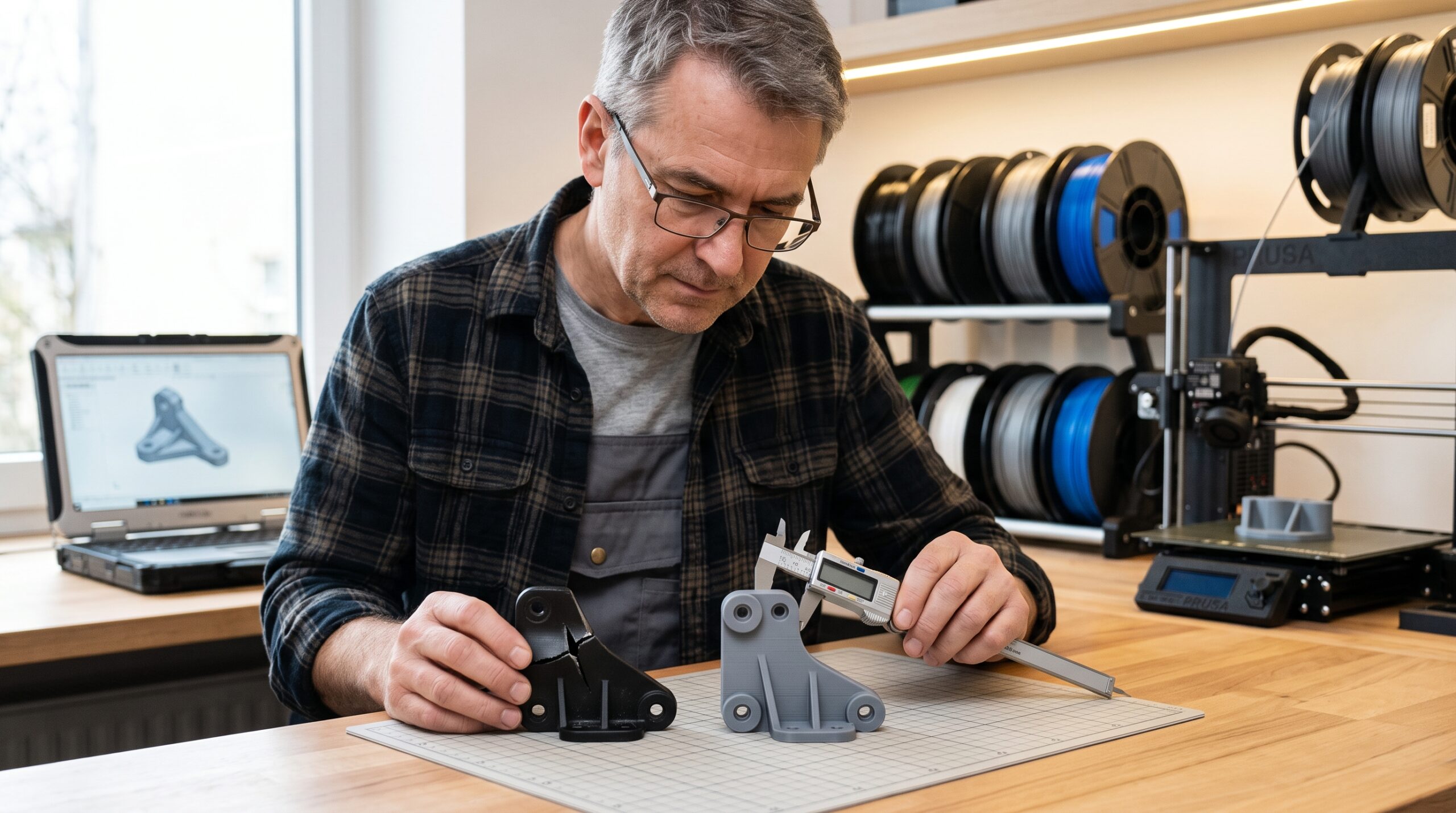
- Are the mounting holes aligned?
- Does the shaft fit?
- Is the clip too tight?
- Does a mating curve contact correctly?
- Is there enough clearance for installation?
- Can the part move through its intended range?
Sometimes I do not even need to print the entire part. A mounting face, clip section, hole coupon, or mating surface may provide the answer faster.
That is the thinking behind my controlled replacement-part test-fit method.
Step 7: Validate the Final Configuration
A prototype that fits does not automatically prove that the completed part will survive every condition in which it will be used.
The final check should consider the actual material, print orientation, hardware, expected movement, temperature, vibration, moisture, installation method, and consequence of failure.
That last point is especially important.
A good project evaluation should be willing to conclude that 3D printing is not the right solution.
What Parts Are Often Worth Evaluating?
Some of the most promising custom projects are annoyingly ordinary parts that manufacturers no longer sell separately.
If your broken component falls into one of those categories, also see my broken brackets and clips replacement guide and discontinued plastic parts service page.
Use This Five-Minute Replacement-Part Planner
1. What does the part do?
Describe its function in one sentence.
2. What connects to it?
List every screw, clip, shaft, slot, mating surface, or neighboring component.
3. Why do you think it failed?
Cracking, impact, heat, flexing, wear, overtightening, unknown?
4. What environment does it live in?
Indoor, outdoor, vehicle, machine, moisture, vibration, sunlight, chemicals, heat?
5. What happens if the replacement fails?
Minor inconvenience—or risk to equipment or people?
6. What evidence do you have?
Original part, fragments, photographs, dimensions, CAD file, drawing, mating component?
Those answers are more useful to me than simply knowing the weight of the finished print.
Have a Broken Part You Cannot Replace?
You do not need to arrive with a finished STL. A project can begin with the original component, broken pieces, clear photographs, measurements, a sketch, STEP/STL/OBJ files, or a description of what the part needs to accomplish.
Start a Project Review See What to MeasureWant to Learn the Complete Process Yourself?
The same problem-first thinking works when you own the printer.
P.R.I.N.T. It: Practical 3D Printing for Beginners brings printer setup, slicing, materials, calibration, measuring, troubleshooting, replacement-part planning, maintenance, and the P.R.I.N.T. Method™ into one structured reference.
It is designed to help you make decisions instead of randomly changing settings until something works.
Explore P.R.I.N.T. ItQuick Knowledge Check
1. Should a replacement part always be an exact copy of the broken original?
No. Important interfaces may need to remain tightly controlled, but an obvious weak area can sometimes be reconsidered when the application, available space, requirements, and risk allow it.
2. Why isn’t 100% infill automatically the best strength fix?
Because failure can involve geometry, print orientation, fasteners, layer bonding, material, fit, load direction, or another factor that additional infill does not correct.
3. What should be measured first?
The interfaces that determine fit and function: mounting surfaces, holes, shafts, clips, slots, spacing, clearances, mating curves, and the overall space available for the part.
4. Is a successful first test fit proof that the design is finished?
Not necessarily. Final validation may still need to consider the intended material, orientation, fasteners, load, movement, heat, weather, vibration, and actual operating environment.
Frequently Asked Questions
Can you make a 3D-printed replacement from a broken original?
Often, yes. Broken pieces can still provide valuable dimensions and geometry. Photographs, measurements, mating components, drawings, or an undamaged matching part can help fill in missing information. Feasibility depends on how much useful reference geometry remains and what the replacement must do.
Do I need an STL file before requesting a quote?
No. Many custom projects begin with a broken physical part, photographs, measurements, a sketch, or another digital file format. The first step is determining whether the geometry can be reconstructed accurately and whether custom manufacturing is practical.
Are 3D-printed replacement parts strong enough for real use?
They can be useful for many functional applications, but suitability depends on much more than the filament name. Geometry, material, orientation, print process, fasteners, load, environment, fit, and consequences of failure all matter.
Can a 3D scanner automatically make the replacement?
No. Scanning can capture useful surface geometry, particularly complex shapes, but the resulting mesh may still require cleanup, measurement, CAD reconstruction, missing-feature repair, tolerances, and physical test fitting.
How many prototypes will a replacement part require?
There is no fixed number. A simple component with clear dimensions may fit immediately. A damaged part with clips, moving features, hidden surfaces, or several mating interfaces may need controlled revisions. The goal is to answer uncertainties efficiently rather than chase an arbitrary prototype count.
When should I buy an original replacement instead?
If a genuine replacement is readily available, reasonably priced, correctly rated for the application, and easy to install, it may be the simplest choice. Custom printing makes the most sense when it solves a problem that ordinary replacement options do not solve well.
A Better Replacement Begins With a Better Question
Custom 3D printing is not valuable because a printer can copy plastic.
It is valuable because a broken component can be studied, measured, modeled, tested, and—when appropriate—rethought.
The question is not simply, “Can I print this?”
It is, “What does this part actually need to do, and what is the most practical way to make the next one?”
That is the difference between replacing a shape and solving the problem.
Have you ever had one tiny plastic part make an otherwise good product useless? Tell me what broke in the comments. Those everyday failures are often some of the most interesting 3D-printing problems to investigate.
