
Functional 3D Printing · Fit and Tolerance Guide
The parts slide together. The screw holes line up. Nothing is obviously broken. Yet the assembly rocks, rattles, twists, or slowly works loose. That is usually not a strength problem—it is an interface problem.
After years of printing brackets, holders, prototypes, organizers, and replacement parts, I have learned that “it fits” is only the first test. A useful part also needs the right amount of clearance, support, alignment, and restraint for the job.
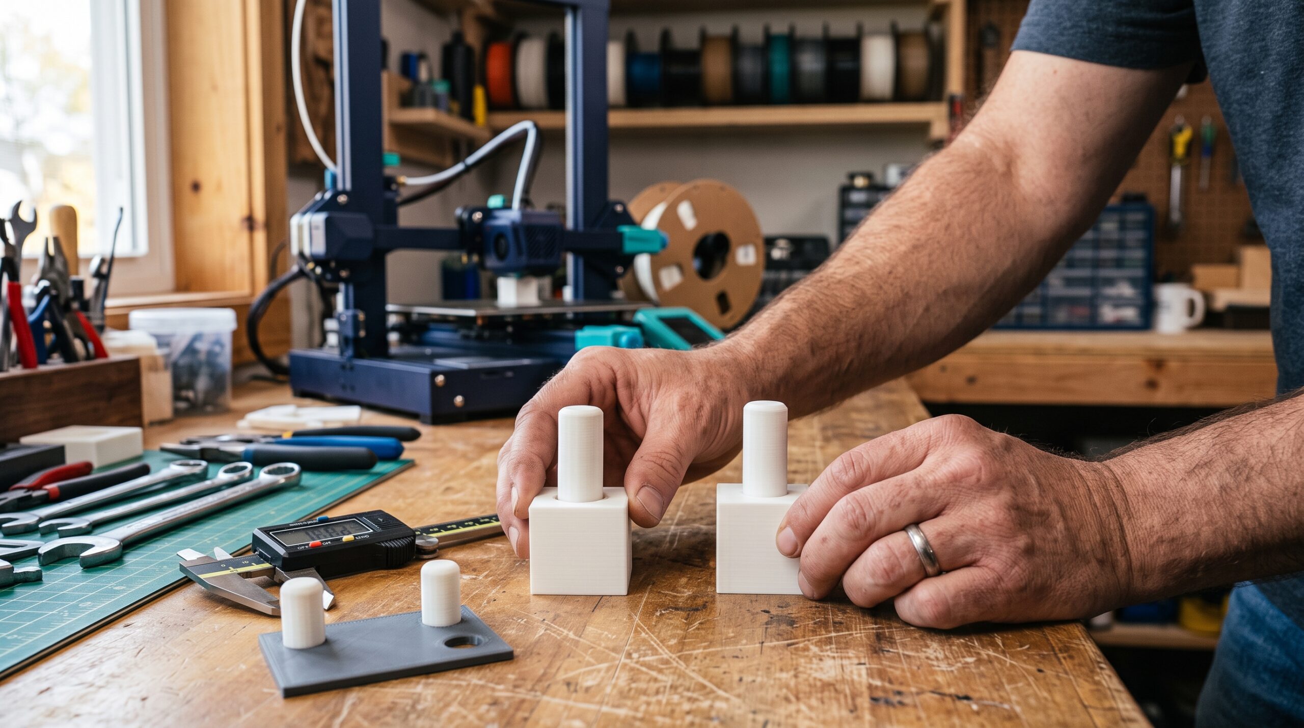
A 3D-printed assembly can wobble even when its dimensions appear correct because fit is controlled by more than one measurement. Clearance, contact length, hole shape, layer orientation, first-layer expansion, material flexibility, fastener preload, and printer repeatability all affect the result.
Do not immediately add more infill or shrink every gap. Identify the moving interface, print a small tolerance test, change one variable, and test again.
“Fits” and “functions” are not the same result
A peg entering a hole proves only that the peg can enter the hole. It does not prove that the joint will stay centered, resist twisting, survive repeated use, or remain stable after the material warms up.
This is why a part can pass an exciting first test and still disappoint in service. The problem often hides at the interface: the exact place where one part touches, slides over, clamps against, rotates inside, or fastens to another.
If you are recreating a missing or broken component, begin with my guide to measuring a part for 3D printing. Then use the process below to turn those measurements into a controlled fit.
The four fit problems that makers often treat as one
Clearance
The intentional space between mating surfaces. Too little can seize; too much can rattle.
Alignment
How well the features share the intended centerline, plane, or mounting position.
Support
How much contact length or bearing area keeps the connection from rocking under load.
Retention
What prevents the parts from separating: friction, a clip, a shoulder, a screw, or another feature.
Material behavior
Flex, creep, heat, wear, and moisture can change the fit after the first successful assembly.
Process variation
Extrusion, cooling, first-layer compression, orientation, and surface texture affect real dimensions.
The National Institute of Standards and Technology notes that additive manufacturing creates distinct challenges for dimensional and geometric accuracy. In practical terms, the CAD value is a target—not a guarantee that every printed surface will land at that exact measurement.
A simple way to picture 3D print tolerances
Fit spectrum
Important: There is no universal clearance number for every FDM printer, material, geometry, orientation, and use. Treat any starting value as a test condition—not a promise.
Prusa’s official design guidance makes the same practical point: two parts designed at zero tolerance will probably not slot together as intended, and designers should expect to adjust tolerances and geometry. That is why a small test coupon is usually more useful than copying a clearance value from a stranger’s printer.
Why your part wobbles: diagnose the motion first
| What you observe | Likely interface problem | First useful test | Avoid doing this first |
|---|---|---|---|
| The peg rocks inside the hole | Too much radial clearance, short engagement, or an out-of-round hole | Print a short peg-and-hole coupon with several controlled gaps | Increasing infill across the entire part |
| A bracket twists on one screw | The fastener locates one point but does not resist rotation | Add a second locating feature, shoulder, flat, or wider mounting face | Overtightening the same screw |
| A sliding part rattles but sometimes binds | Uneven surface texture, poor alignment, warping, or inconsistent clearance | Check the guide surfaces at several positions and inspect the sliced path | Shrinking the entire channel uniformly |
| The assembly starts tight, then loosens | Wear, creep, flex, heat, or compressed contact points | Cycle the joint under realistic load and temperature | Judging the part only during the first minute |
| The bottom fits differently from the top | First-layer expansion, taper, cooling effects, or vertical misalignment | Measure the feature at multiple heights and compare orientation | Editing the nominal CAD dimension before locating the error |
Seven practical causes of a loose or unstable fit
1. The joint has clearance but not enough guidance
A short peg in a shallow hole can tilt even when the diameter is close. Extending the engagement length, adding a second guide, or increasing the bearing surface may control motion better than simply tightening the diameter.
2. One fastener is being asked to locate and lock everything
A screw can clamp two surfaces together, but a single round fastener does not always prevent rotation. A tab, keyed flat, shoulder, locating pin, second fastener, or shaped mounting face can carry the side load while the screw supplies clamping force.
If the plastic is cracking around the joint, read why 3D-printed parts crack around screws before tightening harder. More torque can turn a fit problem into a broken boss.
3. The first layer changes the interface
A heavily compressed first layer can spread beyond the intended outline. On a cosmetic base this may be harmless. On a mating edge, slot, hole, or locating shoulder, that small lip can push the entire assembly out of alignment.
Inspect the bottom perimeter closely. If the interference exists only near the build plate, correct the first-layer condition or use a deliberate edge treatment rather than enlarging the whole model.
4. Printed holes are not ideal CAD circles
A slicer converts a circular wall into toolpaths, then the extrusion, cooling, seam, layer height, and orientation influence the printed shape. A caliper reading across one direction may therefore miss a tight spot or an oval feature.
Check the feature in more than one direction and at more than one height. If a fastener must pass freely, test it with the actual hardware—not only with a nominal diameter on the screen.
5. The part flexes around the interface
The fit may be accurate while the surrounding wall, arm, or flange bends. In that case, reducing clearance does not fix the real problem. A rib, shorter lever arm, thicker transition, better load path, or different orientation may be more effective.
6. Material behavior changes after assembly
Plastic is not perfectly rigid or dimensionally frozen. Repeated load, sustained clamping, heat, moisture, and abrasion can change how an interface behaves. A fit that feels excellent on the bench may loosen in a hot car or after hundreds of cycles.
Choose the material around the environment and consequence of failure. My replacement-part test-fit guide explains why a controlled prototype is evidence, not wasted filament.
7. The printer is inconsistent before the design is wrong
Loose belts, inconsistent extrusion, wet filament, unstable temperatures, a poor first layer, or a profile that pushes speed beyond repeatable quality can make one sample fit and the next one fail.
Before adding permanent compensation to the CAD model, return to a dependable baseline. These are the 3D printer settings I use as a practical starting point.
Do not treat a successful tolerance coupon as proof that a printed part is safe for personal support, pressure, fuel, flame, high voltage, medical use, or another high-consequence application. Dimensional fit is only one part of suitability.
My P.R.I.N.T. Method™ for fixing a wobbly assembly
- Problem: Describe the unwanted motion. Does the part rock, rotate, slide, rattle, lift, or loosen over time?
- Requirements: Define how the joint should behave, what load it sees, how often it moves, and what happens if it fails.
- Interfaces: Mark the surfaces and features that locate, guide, clamp, support, and retain the part.
- Next-Best Materials & Methods: Decide whether clearance, geometry, hardware, orientation, material, calibration, or another manufacturing process is the practical lever.
- Test & Tune: Print the smallest coupon that isolates the uncertain feature. Measure it, assemble it, cycle it, record the result, and change one variable.
Test the interface, not the whole object. If the uncertainty is a 12 mm peg and hole, you usually do not need to reprint a six-hour housing to learn whether the next clearance works.
A better tolerance test in five steps
- Use the real printer, nozzle, material, layer height, and orientation. A coupon from another setup may answer a different question.
- Put several controlled variations in one small test. Label each feature in the model so you can identify it after printing.
- Let the part cool before judging it. A warm part can flex or measure differently.
- Test the real motion and hardware. Slide it, rotate it, tighten it appropriately, or cycle it as the final part will be used.
- Save the result with the profile. Record the material, printer, orientation, date, and winning geometry instead of relying on memory.
For a low-risk household part, a sensible experiment might compare three or four nearby clearances. The winning value is the one that meets the actual requirement consistently—not necessarily the tightest sample you can force together.
Which adjustment should you make first?
| Adjustment | Best used when | Main advantage | Main risk |
|---|---|---|---|
| Change the CAD clearance | The error is repeatable and isolated to a mating feature | Direct control over the intended interface | Can hide a printer problem if used too early |
| Add engagement length or a guide | The joint tilts or rotates despite acceptable clearance | Controls motion without making assembly excessively tight | May add friction, size, or support needs |
| Add a fastener or locating feature | The assembly needs positive retention or anti-rotation | Separates location from clamping | Poor boss design or overtightening can crack layers |
| Use slicer compensation | A calibrated profile shows a consistent feature-size bias | Can correct repeated process behavior | A global setting may alter unrelated features |
| Change orientation | Roundness, layer steps, strength direction, or support surfaces matter | Can improve geometry and load path together | May move the problem to another surface |
| Post-process the interface | A drilled, reamed, sanded, tapped, or inserted feature is appropriate | Useful for controlled final sizing | Removes material and can reduce repeatability without a process plan |
Affiliate disclosure: The following material link is a partner link. If you make a purchase, I may receive a commission at no additional cost to you. I recommend materials only when they fit the job; filament cannot compensate for poor interface design or an uncalibrated process.
If you need dependable filament for controlled test prints, you can explore COEX 3D materials and use code 3DPRINTINGBYKEVIN for 15% off. Keep the same spool, profile, and environmental conditions through a comparison so the test remains meaningful.
Use this one-project fit planner
P.R.I.N.T. fit-and-tolerance planner
Record: printer ______ material ______ nozzle ______ layer height ______ orientation ______ date ______
Want the complete planning workflow beside your printer? P.R.I.N.T. It: Practical 3D Printing for Beginners connects setup, slicing, materials, calibration, troubleshooting, replacement-part planning, and test documentation in one practical guide.
Four-question knowledge check
1. A peg enters its hole but rocks sideways. What should you check before adding infill?
Answer: Check radial clearance, engagement length, hole shape, alignment, and the surrounding geometry. Infill may not control movement at the interface.
2. Why is a universal “perfect clearance” value unreliable?
Answer: Printer condition, nozzle, material, profile, orientation, geometry, cooling, surface texture, and required fit all affect the result.
3. What is usually the most efficient next print when one mating feature is uncertain?
Answer: A small, labeled tolerance coupon that reproduces the real interface with the real printer, material, profile, and orientation.
4. Does a successful fit test prove that a part is safe for a high-consequence use?
Answer: No. Fit is only one requirement. Strength, fatigue, heat, chemicals, manufacturing consistency, inspection, regulations, and consequences of failure may require qualified engineering and another process.
Frequently asked questions
Should I make a loose 3D-printed fit tighter in CAD or in the slicer?
Use CAD when the change belongs to a specific functional interface. Consider slicer compensation only after testing shows a consistent process bias that you understand. A global slicer adjustment can affect features that were already correct.
Why do my holes print smaller than the model?
Toolpath geometry, extrusion behavior, cooling, seams, layer height, orientation, first-layer conditions, and printer calibration can all affect the result. Measure in multiple directions, inspect the sliced preview, and print a controlled hole test before changing the complete part.
Will more walls fix a wobbly 3D-printed part?
More walls can stiffen thin surrounding geometry, but they do not automatically correct excessive clearance, short engagement, misalignment, or missing retention. Diagnose where the motion originates first.
Is a press fit always stronger than a sliding fit?
No. A press fit can create useful friction, but excessive interference may split the part, distort the assembly, or make results inconsistent. The correct fit depends on load, geometry, material, orientation, assembly method, service conditions, and failure risk.
When should I ask for help with a replacement part?
Ask for help when the original is incomplete, the interfaces are difficult to measure, material or process selection is uncertain, repeatable quantity matters, or failure could damage equipment or hurt someone. A project review can determine whether in-house FDM, a design revision, or another manufacturing method makes sense.
Your next print should answer one clear question
Do not keep tightening a screw, changing random settings, or reprinting the entire object. Find the moving interface. Build the smallest useful test. Let the result guide the next change.
Start a Project Review Explore the P.R.I.N.T. It Ebook
What fit problem gives you the most trouble—holes, sliding joints, snap features, or screw-mounted parts? Share what you are seeing in the comments. Include the printer, material, and direction of the unwanted movement so the discussion can start with evidence.
Sources and further reading
