
An STL file can look perfect on your screen and still produce the wrong part.
The printer can complete every layer without an error. The surface can look clean. The dimensions can be close. And after several hours of printing, you can still pick up the part and discover that the hole is too tight, the clip breaks in the wrong direction, or the mounting face does not sit where it should.
That is why I do not think of reliable 3D printing as pressing Print.
I think of it as a chain of decisions—from the digital file to the slicer, material, orientation, first layer, test print, inspection, and finally the real-world job the part was supposed to accomplish.
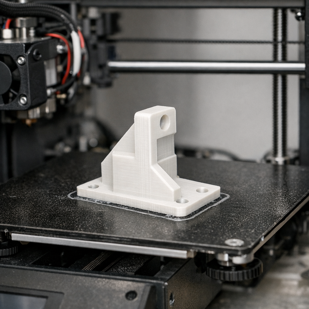
What is the most reliable way to go from STL to a finished 3D print?
Verify the model and its scale first. Choose the material and print orientation around the job the part must perform. Inspect the sliced layers rather than trusting the 3D preview, establish a clean first layer, and test the riskiest fit or feature before committing to a long print or production batch.
After printing, measure and test the physical part. A completed print is evidence—not proof that the design is correct.
Affiliate disclosure: Some links in this guide are affiliate or partner links. If you purchase through them, I may earn a commission at no additional cost to you. Recommendations are included because they fit the workflow—not simply because they are products I can link to.
The Difference Between “It Printed” and “It Worked”
A decorative model gives you some freedom. If it is 1 mm wider than expected, nobody may care.
A bracket, clip, holder, spacer, enclosure, gear cover, or replacement component is different. Those parts have interfaces. They touch, slide, bolt, snap, locate, support, or clear something else.
| Hope-and-Print Workflow | Reliable Workflow |
|---|---|
| Download the STL and press Print | Verify scale, geometry, dimensions, and intended use first |
| Choose the orientation that looks easiest | Orient around load direction, supports, finish, and fit |
| Use whatever filament is already loaded | Match material to heat, flex, environment, and load |
| Trust the completed slicer image | Scroll through the actual layers and toolpaths |
| Start the full print immediately | Test uncertain interfaces before spending hours printing |
| Judge success by appearance | Measure, install, load, move, and test the finished part |
My Reliable STL-to-Part Workflow
Verify the file before touching printer settings
Start with the model.
Not the nozzle temperature. Not the infill pattern. Not the maximum speed.
Confirm that you actually have the right file, at the right scale, with geometry that represents a printable object.
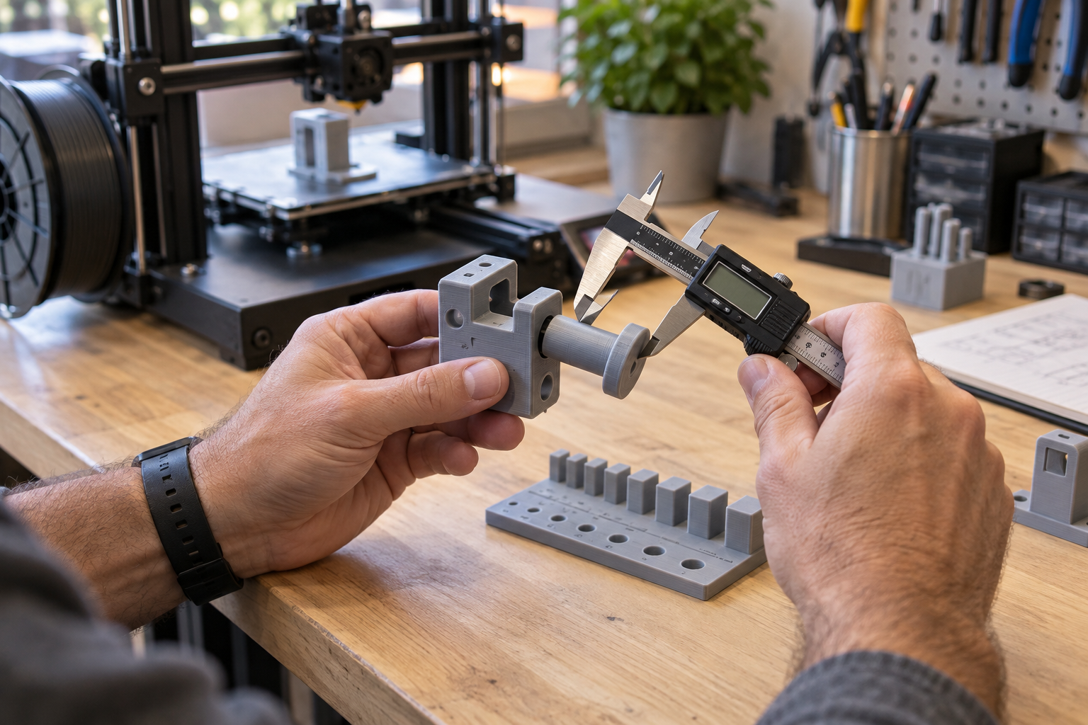
I check the overall dimensions and then focus on the features that can make the whole job useless:
- Mounting-hole diameter and spacing
- Shaft or bearing locations
- Slots and tabs
- Snap fits
- Wall thickness
- Mating surfaces
- Clearances around moving components
If you are recreating a real object, my guide to measuring a part for 3D printing goes deeper into the dimensions worth protecting.
Do not assume STL is the only file format worth using
STL remains extremely useful because almost every slicer understands it. For a simple mesh, it often does exactly what you need.
But STL is not the only option anymore.
When my workflow supports it, I also consider 3MF because it was designed for additive manufacturing and can preserve defined units and additional model information that a basic STL workflow does not carry.
You can read the current 3MF Consortium documentation. If you design in Shapr3D, its current export documentation lists STL and 3MF among its 3D-printing formats.
Choose the material from the job backward
“Print it in PLA” is not a complete material decision.
PLA is excellent for many prototypes, organizers, fixtures, indoor parts, and general learning. But a material should be chosen around the environment and the way the part will be used.
| Part Requirement | Question I Ask |
|---|---|
| Indoor prototype | Would straightforward PLA meet the actual requirements? |
| Repeated flexing | Does the material tolerate the movement without cracking? |
| Heat exposure | Could the part soften, creep, or distort? |
| Outdoor use | How will UV, moisture, and temperature swings affect it? |
| Functional load | How will material and layer direction work together? |
| Chemical exposure | Is the material compatible with what may contact it? |
I use COEX filament in my own workflow. If you purchase there, code 3DPRINTINGBYKEVIN may provide 15% off; confirm the discount at checkout.
Choose orientation before chasing infill
Rotation is not merely a way to make a model fit on the bed.
Turn a functional part and you can change where the layer interfaces sit relative to the load. You can also change support requirements, dimensional accuracy, appearance, print time, and which surfaces touch the build plate.
If a clip repeatedly fractures along the layer direction, simply increasing infill may miss the real problem.
Sometimes the better answer is to rotate the part, strengthen the geometry, change the wall strategy, or redirect the force through the component.
For a deeper design-focused workflow, see From 3D Design to Finished Part.
Use the slicer preview as an inspection tool
This is one of the cheapest quality-control steps you have.
Before the machine consumes one gram of filament, scroll through the sliced layers.
Look for walls that disappear, odd gaps, unexpected solid sections, unsupported islands, excessive supports, incorrect scale, questionable first-layer contact, misplaced seams, and features that become only one extrusion wide.
I also verify that the selected printer, nozzle, build plate, and material profile match the machine in front of me.
- Correct printer and nozzle selected
- Correct material profile loaded
- Model scale confirmed
- Orientation intentional
- Walls and thin features visible
- Supports appear where expected
- First-layer footprint makes sense
- Print time and material estimate are believable
If something looks strange in preview, investigate it before pressing Print. A slicer warning that costs five minutes to understand can save hours of machine time.
Watch the first layer like it owes you money
The first layer does not guarantee a successful print, but a bad one can end the job before it really begins.
I want neighboring extrusion lines to meet cleanly without loose gaps, excessive ridges, nozzle scraping, or sections that are already lifting from the plate.
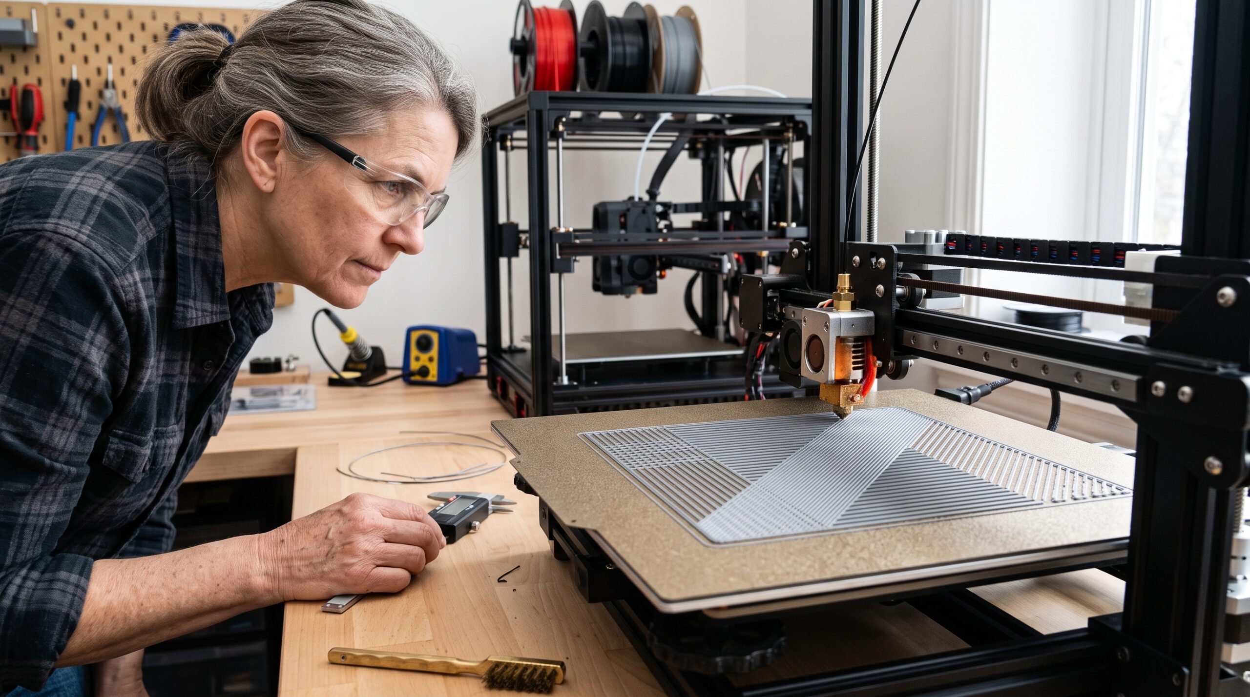
If your first layer is inconsistent, go back to the fundamentals: correct build surface, clean plate, machine calibration, Z-offset where applicable, correct material profile, and an unobstructed filament path.
My beginner’s calibration guide explains why calibration works better as a sequence than as a pile of random test prints.
Print the risky feature before printing the whole part
This habit can save more filament than a dozen clever slicer tricks.
If I am uncertain about one mounting hole, snap tab, shaft fit, hinge, clearance, or mating surface, I do not always need the complete object to answer the question.
I can print the uncertain section.
Then I can put it against the actual hardware, measure it, and see what reality says.
That small test is not wasted filament. It is inexpensive information.
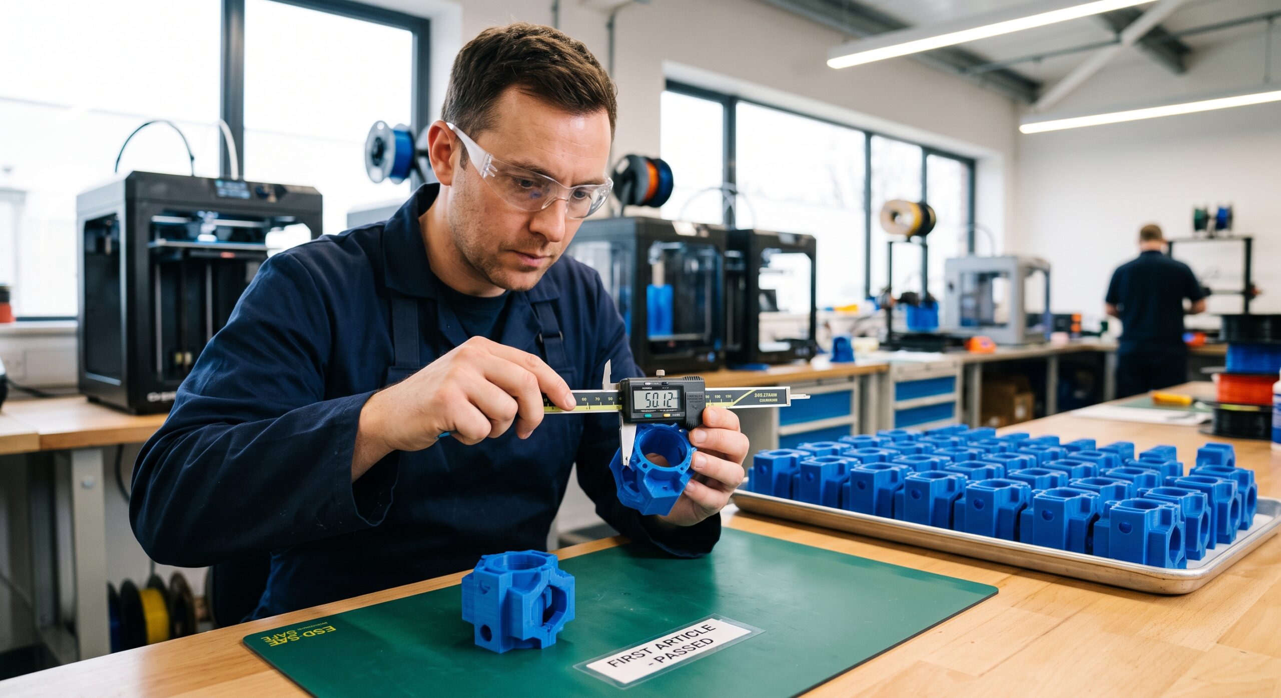
This becomes even more important when you move from a single prototype to repeated parts.
The printer finishing is not the final quality check
When the machine stops, inspect the physical result.
Remove supports carefully. Look at critical surfaces. Measure dimensions that matter. Check holes. Check alignment. Install the part where possible.
Then use it.
A beautiful bracket that does not line up with the screws is a bad bracket.
A cosmetically rough prototype that proves all four mounting points and identifies one clearance problem may be an extremely successful prototype.
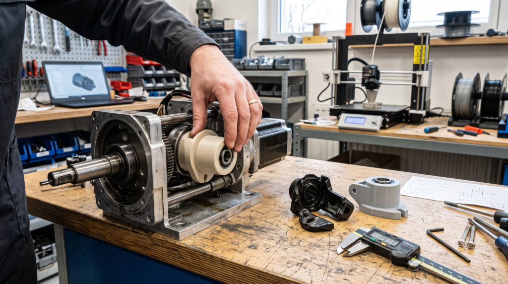
Read Why 3D-Printed Replacement Parts Need a Test Fit if you are working with functional or discontinued components.
Use the P.R.I.N.T. Method™ Before You Press Print
I use the P.R.I.N.T. Method™ to keep a job centered on the physical problem rather than getting distracted by settings and hardware.
Your STL-to-Finished-Part Planner
If you want the complete beginner-friendly system, see P.R.I.N.T. It: Practical 3D Printing for Beginners.
When the Print Fails, Preserve the Evidence
Do not immediately change five slicer settings.
Look at where the failure started.
Did it begin on the build plate? Did extrusion slowly disappear? Did one corner curl upward? Did the entire layer suddenly shift sideways? Did the part print perfectly but break during installation?
Those are different failures and deserve different tests.
| Symptom | Check First |
|---|---|
| First layer will not stick | Plate condition, selected plate/profile, calibration, first-layer height |
| Weak or missing extrusion | Spool movement, filament path, material profile, nozzle restriction |
| Stringing or blobs | Filament condition and temperature before aggressive retraction changes |
| Warped corners | First layer, drafts, footprint, cooling, material behavior |
| Part breaks in service | Orientation, walls, layer bonding, geometry, material, actual load |
| Part looks good but will not fit | Critical dimensions, clearances, first-layer effects, test-fit strategy |
For a more complete symptom-based process, use my 3D printing troubleshooting guide.
Buying Better Hardware Does Not Replace the Workflow
Modern printers have made 3D printing dramatically easier.
Automatic calibration, input shaping, filament sensors, improved slicers, better motion systems, cameras, and increasingly sophisticated failure detection can remove a lot of tedious setup.
That is good progress.
But a printer still does not know whether your bracket should clear a nearby screw by 0.6 mm or whether the tab you designed is going to be flexed fifty times per week.
Automation can help a printer reproduce the file.
It cannot decide whether the file represents the right part.
If you are comparing newer machines, you can browse the Creality official store. If reverse engineering is part of your workflow, you can also see the current 3DMakerpro scanner lineup.
Neither is a requirement for following the workflow in this article.
Quick Knowledge Check
Open each answer after choosing what you think is correct.
1. An STL slices without errors. Does that prove the finished part will fit?
No. Successful slicing tells you the slicer can generate a toolpath. It does not verify scale, clearances, mounting dimensions, material behavior, or real-world fit.
2. A snap tab keeps breaking along the layer lines. Should you automatically increase infill?
No. First inspect orientation, load direction, wall geometry, material, and layer bonding. More infill may do little if the load is trying to separate weakly oriented layers.
3. Why print only one risky feature instead of the complete model?
To answer the uncertain question cheaply. A small fit coupon can verify a hole, shaft, clip, slot, or clearance before you spend hours printing the complete object.
4. When is a prototype that does not fit still useful?
When it produces controlled information. If it reveals exactly which clearance, dimension, or feature requires revision, the prototype has done useful work.
Frequently Asked Questions
Should I use STL or 3MF for 3D printing?
STL remains widely compatible and works well for basic mesh geometry. 3MF can preserve defined units and additional manufacturing information. Use the format that best preserves the information your actual workflow requires, and keep the editable CAD file when future dimensional changes may be needed.
Why does my STL look correct but print at the wrong size?
Check the original export dimensions and the units assumed when the file was imported. Do not blindly rescale a functional part until you know why the mismatch occurred, because scaling changes every interface at the same time.
How do I know whether an STL is printable?
Open it in the slicer, verify scale and orientation, and inspect the generated layers. Look for missing walls, broken geometry, unsupported features, unreasonable supports, thin details, and unexpected gaps. Printability also includes whether the physical design makes sense for the intended material and job.
Do I need to calibrate before every print?
No. Use the procedures appropriate for your machine and recalibrate when the printer, nozzle, plate, material profile, hardware, or print evidence gives you a reason. Repeatedly recalibrating unrelated systems can create more variables rather than fewer.
How can I make functional 3D prints more reliable?
Concentrate on interfaces, wall structure, material, orientation, first-layer consistency, critical dimensions, and testing. Reliable functional printing usually improves faster when you measure and test intentionally than when you simply increase infill or reduce print speed.
Should I print the entire replacement part as my first prototype?
Not necessarily. If one uncertain feature determines whether the part can work, isolate and test that feature first. Once the critical interface is proven, move to the complete prototype.
The Finished Part Gets the Final Vote
A clean STL is useful.
A perfect slicer preview is useful.
A printer that completes the job without an error is useful.
But none of those things are the actual goal.
The goal is the moment you take the finished piece to the cabinet, machine, tool, appliance, fixture, prototype, or broken assembly that started the project—and it fits, moves, holds, clears, supports, or replaces what it was supposed to.
That is reliable 3D printing.
If you have an STL, STEP file, sketch, broken part, scan, measurements, or simply a problem you think 3D printing might solve, use my Project Quote & Intake form. I can help determine whether there is a practical path from the digital idea to a useful physical part.
What Part Are You Trying to Get Right?
Leave a comment below and tell me what you are printing, which material you are using, and where the project is giving you trouble.
If the STL looks perfect but reality keeps disagreeing, tell me what is happening. Those are often the most useful problems to work through.
